What is new in version 6.2
Each new version of MatrixFrame® includes improvements and enhancements designed to make construction faster, better, more efficient, and enjoyable. Below are the highlights of the key updates in MatrixFrame® version 6.2. A complete overview of all improvements and changes can be found in the Release Notes.
MatrixFrame
Eccentric shift of the support(s) for 2D-Grillage
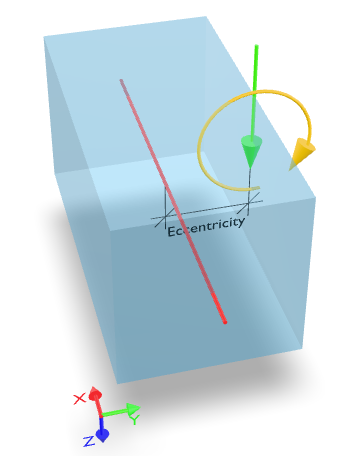
The eccentricity of the support refers to a shift in the member axis placement of the support position on the local Y' coordinate of the member. This shift can be defined as either a positive or negative value:


The input of eccentric shift data is presented in the support definition window and the advanced support properties grid table.
The structure drawing represents the local eccentric shift of the support, such as displacing the support eccentrically to the central axis of the beam/member.
The analysis calculation of the member-located supports aims to account for the appearance of torsional force because of the eccentrically placed support. With the eccentric supports defined, the advanced analysis option of the reduced torsion is neither meaningful nor encouraged.
Read more: Supports definition
Eccentric shift of the loads for 2D-Grillage
An eccentrically applied load describes the shift of the loading axis relative to the axis of the cross-section in the direction of the local Y-axis of a member:


The input of eccentric shift data is presented in the loads definition window and the grid table.
The local eccentric shift of the load is represented on the structure drawing, like a pair of loads: the concentrically placed concentrated load and the additional torsional moment load appearing due to the eccentricity.
The analysis calculation of the member-located eccentrically placed loading aims to account for the appearance of torsional force because of the eccentrically placed load. With the eccentric loads defined, the advanced analysis option of the reduced torsion is neither meaningful nor encouraged.
Read more: 2D-Grillage specific eccentric placement of the loads
Snow load calculation modification because of solar panels
The snow load generator solar panel placement choice can be manually selected/deselected on the member by pressing the "Solar panel" toggle button control:

Snow load shape coefficient µ1 for the tilted solar panel using member-applied solar panel
The snow load shape coefficient µ1 for the tilted solar panel arrangement is taken as limit value µ1 = µp = 1 (PrEN 1991-1-3#7.5.2(7.5) ) assuming γ factor of 2 kN/m3, Sk = 0.7 kN/m2, and the default solar panel height ≥ 350 mm.
The modification of the shape coefficient µ1 for the solar panel can be chosen only on the roof or its part has an inclination angle α ≤ 5°.
Wind load generation for Multispan roofs under the requirements of NEN-EN 1991-1-4#7.2.7
Multispan roofs are detected automatically, requiring no user intervention. Roofs can be classified as Multispan if the building has at least two spans.

The Multispan roof structure must consist of regularly repeating Monopitch or Duopitch roof types.
Roof types allowed in the Multispan load generator:


Note: Be attentive and ensure the correct roof type and wind direction are set. If the initial load generator settings are incorrect, make the necessary adjustments.
A mix of Monopitch and Duopitch roof types is prohibited within the same structure.
Variations in rooftop or roof-bottom altitudes are not allowed within the same structure.
New load combination scenario generating load combinations for the favorable permanent load when acting with wind actions
The additional wind combination rule, "Favorable Permanent + Wind", is included as an option for combination scenario selection. This newly introduced rule is disabled by default and can be turned on by user action:

Counterclockwise rotation of the member around its local X' axis by specifying the rotation angle γ in the "Member" table

The member rotation angle γ [°] is available only in the 3D-Frame, 1.5D, and 2.5D packages.
The member rotation angle does not affect the geometric characteristics of the member, but it does influence the overall stiffness of the computational system.
When the member is rotated by angle γ, all properties related to its local axes, such as the cross-section and local loads acting on it, are rotated as well.
When interpreting the analysis results, consider the member’s local coordinate system rotated by angle γ, as the results are presented relative to this rotated system.
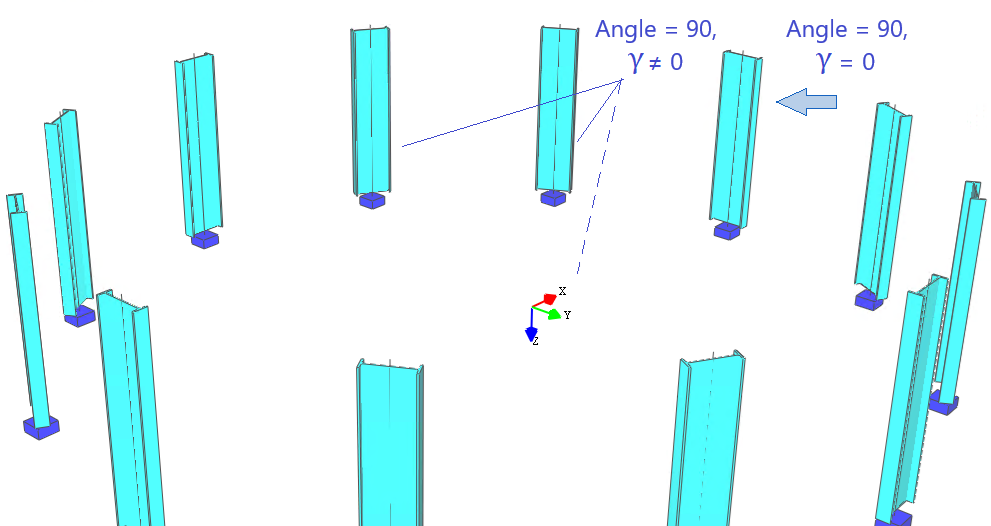
The member rotation angle γ differs from the initial cross-section rotation angle. The initial rotation angle of the member cross-section, assuming γ is equal to 0 (γ = 0), can be defined in the Section definition part. The initial rotation angle of the cross-section is presented in the local cross-sectional axis system and is used to determine the geometric characteristics of the cross-section. This initial rotation angle of the cross-section is universally applied across all packages (1D, 2D, 3D, etc.) as follows:

The interaction of cross-section rotation angle and member rotation angle γ can be treated as:


Read more: Rotation of members
Additional visibility layer setting "Highlight non-active members"
If this setting (under Visibility properties -> Layers -> Structure view) is turned 'On', non-active members will be displayed as system lines only:

Optional report grouping of support reactions by load case type

Without grouping:

With grouping applied:

Conditional splitting of the "Internal Forces & deflections" report into separate reports "Internal Forces" and "Internal Deflections"

Support reactions aligned the support rotation angle
If a support is defined at an angle, the support reactions aligned with the support rotation angle will be presented using bracket notation. When the detailed report option is selected, the report will display the rotation-aligned support reactions.

MatrixTools
New features of the Punching Advanced module
New types of parametrically defined columns have been introduced:
1.1 Rectangle Arc (RA ###x###)

| 
|
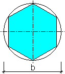
1.2 Polyhedron (P###x#)

1.3 T-Shape (T ###x###x###x###x###)

For more details, refer to the Matrix Frame Knowledge Base: Parametric cross sections
2. The definition of the edge contour for corner column panels has been improved by allowing the specification of reference rotation angles for the first and second edges, labeled as "Edge Angle 1" and "Edge Angle 2."

3. The universal punching calculation method, Beta (EN-NEN 1992-1-1#6.4.3), has been implemented, as outlined in "CT23 Ponsberekening nader beregarding (Normbesef 1)", p. 58.
Read more: Punching calculation advanced