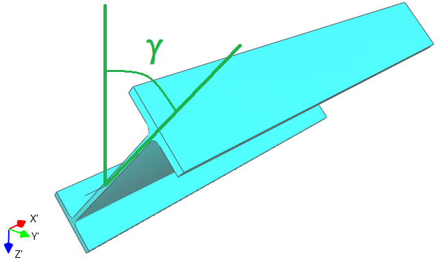
The counterclockwise rotation of a member about its local X′ axis is defined by the member rotation angle γ [°], which is specified in the “Member” grid.
Notes:
1. The member rotation angle γ is available only in the 3D-Frame, 1.5D, and 2.5D project types;
2. This rotation angle does not affect the geometric characteristics of the member, but it does influence the overall system stiffness;
3. When a member is rotated by the angle γ, all properties related to its local axes - such as the cross-section orientation and local loads acting on the member - are rotated accordingly;
4. When interpreting the analysis results, the member’s local coordinate system rotated by the angle γ must be taken into account, since the results are presented with respect to this rotated system.
When interpreting the analysis results, the member’s local coordinate system rotated by the angle γ must be taken into account, since the results are presented with respect to this rotated system.
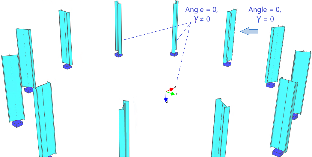
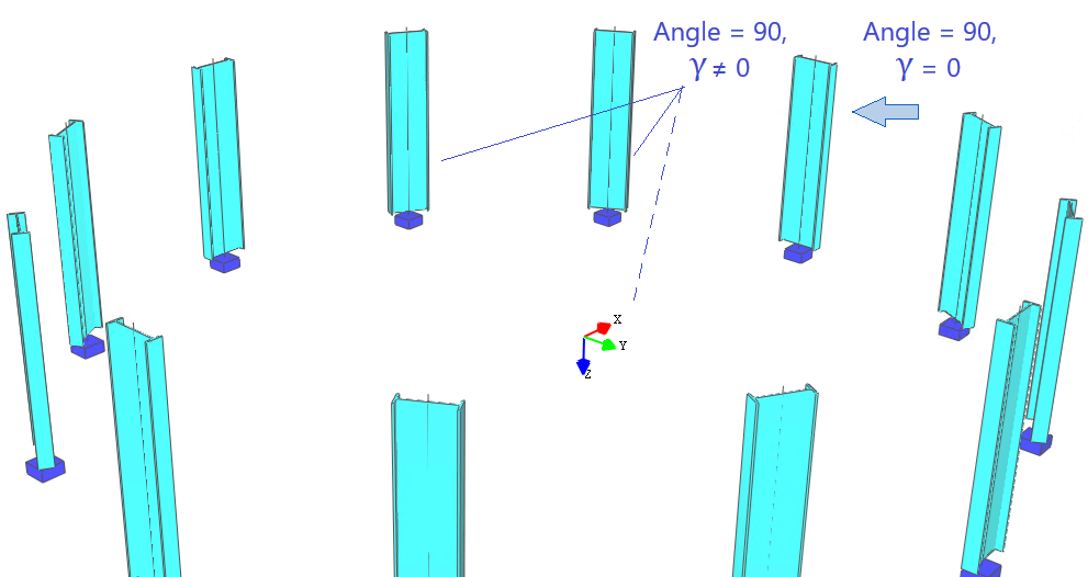
The initial rotation angle of the member cross-section, assuming γ = 0, can be defined in the “Section definition” part. This initial rotation angle is defined in the local coordinate system of the cross-section, and the geometric characteristics of the cross-section depend on this angle.
This angle is applied consistently in all project types (1D, 2D, 3D, etc.) as follows:

The interaction between the cross-section rotation angle and the member rotation angle γ can be treated as: