Connectivity definition
Elastic connectivity joints can be defined:
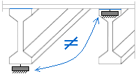
- Only in hybrid 2D-Grillage/Plate structures.
By using of discrete (calculational) modeling, the connectivity between structural beams and plates is treated as the bracing between nodes of the discrete (calculational) model:
In discrete (analytical) modeling, the connectivity between structural beams and plates is treated as a coupling (bracing) between the nodes of the model:
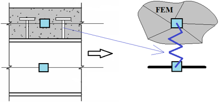
The same interpretation of interaction appears by modeling connectivity of the structural parts of the slab:
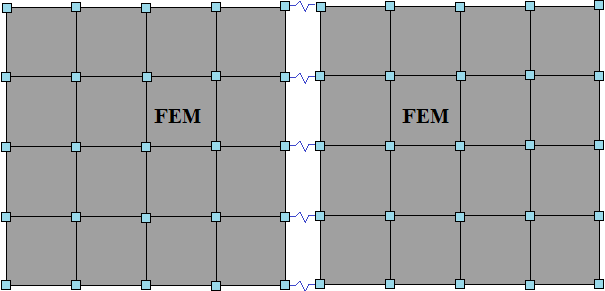
The same interaction behavior applies when modeling the connectivity between slab segments:
The properties of the connectivity are defined by the stiffness values of the zero-length connectivity joint, as follows:
Ex – axial stiffness of the zero-length connectivity in the global X direction [kN];
Ey – axial stiffness of the zero-length connectivity in the global Y direction [kN];
Ez – axial stiffness of the zero-length connectivity in the global Z direction [kN].
The axial stiffness representing a rigid connectivity joint between plates/slabs can be calculated as:
where:
E – Young's modulus [Pa];
h – plate/slab thickness [m];
v – Poisson's ratio.
The flexural stiffness representing a rigid connectivity joint between plates/slabs can be calculated as:
Stiffness values defined between zero and 'rigid' represent a semi-rigid connectivity joint. Conversely, a zero value represents a released (rigidless, free) connectivity joint.