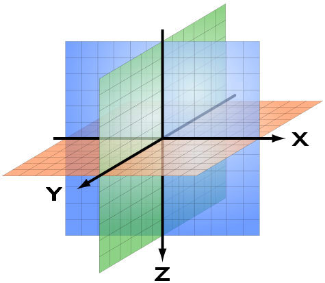
MatrixFrame uses an X-Y-Z coordinate system, with the positive Z-axis pointing downwards. The arrows in the figure below indicate the positive directions of the X, Y and Z axis.
This X-Y-Z coordinate system is used within all modules, both for 1D beams, 2D beam gratings, 2D and 3D frameworks and also within FEM plates and FEM disks. This coordinate system is used for both the global coordinate system and for the local (member or plate) coordinate system.
Rotations
The figure below applies to the directions of rotation. The colors of the directions correspond to the RGB colors: X = Red, Y = Green and Z = Blue
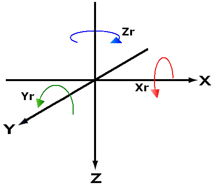
These directions also apply to the local coordinate system. That is the coordinate system within a member or a plate element. These are indicated with an accent, so X 'and Y' and Z 'are the local directions and Xr' and Yr 'and Zr' for the local directions of rotation.

Right hand rule
The global and local orientation of the coordinate system is according to the right-hand rule, both for the directions and for the rotations.
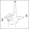
Use the Right-hand rule to determine the positive directions of the X-axis, the Y-axis, and the Z-axis. First make a fist. Then extend the thumb in the direction of the positive X-axis. Then straighten the forefinger. That is the direction of the positive Y-axis. Finally extend the middle finger perpendicular to the thumb and forefinger. That is the positive Z axis.
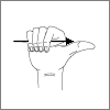
The right-hand rule can also be used to determine the positive direction of rotation per axis. First make a fist. Then point your thumb in the direction of an axis. The curved fingers of the fist then indicate the positive direction of rotation.
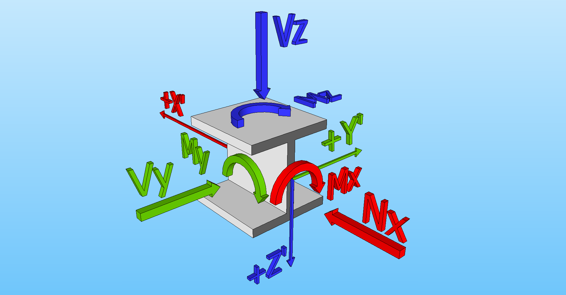
Forces
In the chapter for the input of loads and in the chapter for the calculation results, the following directions also become important. In anticipation of that chapter, see figure below:
Degrees of freedom
MatrixFrame has different project types (analysis models), each with its own specific degrees of freedom:
| Project type | Geometry | Loads | Mechanical results | ||||||||||||
| X | Y | Z | X | Y | Z | Xr | Yr | Zr | Mxx | Myy | Mzz | Vy | Vz | Nx | |
| 1D-Beam | + | - | - | + | - | - | - | + | - | - | + | - | - | + | - |
| 1,5D-Beam | + | - | - | + | + | + | + | + | + | + | + | + | + | + | + |
| 2D-Grillage | + | + | - | - | - | + | + | + | - | + | + | - | - | + | - |
| 2,5D-Grillage | + | + | - | + | + | + | + | + | + | + | + | + | + | + | + |
| 2D-Frame | + | - | + | + | - | + | - | + | - | - | + | - | - | + | + |
| 2D-Truss | + | - | + | + | - | + | - | + | - | - | - | - | - | + | + |
| 2,5D-Frame | + | - | + | + | + | + | + | + | + | + | + | + | + | + | + |
| 3D-Frame | + | + | + | + | + | + | + | + | + | + | + | + | + | + | + |
| 3D-Truss | + | + | + | + | + | + | - | - | - | - | - | - | + | + | + |
| 2D-Plate (FEM) | + | + | - | - | - | + | + | + | - | + | + | - | + | + | - |
| 2D-Wall (FEM) | + | - | + | + | + | + | + | + | + | + | + | + | + | + | + |