A calculation model (bar model) is schematized by means of nodes and bars. The nodes are placed on coordinates. The bar forms the connection between the 2 nodes. Grids can be used to simplify the input. It is not mandatory to use grids. In many cases, it makes it considerably easier to enter.
There are 2 ways of working with grids:
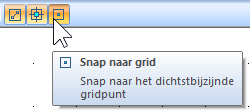
- Grids can be pre-defined, after which nodes / bars can be clicked against grids using a "snap" function.
- The model is sketched at grid points, with MatrixFrame® automatically generating grids. By providing the grid with the correct dimensions afterwards, the calculation model can be introduced with fewer actions and with the correct dimensions.
1. Manual definition of grid lines
Example:
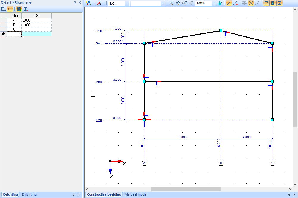
Grid lines can be entered relatively (intermediate) or absolutely. This can be set when defining the grid lines.
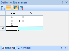 |
Grid lines in X direction with relative dimensions |
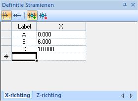 |
Grid lines in the X direction with absolute dimensions |
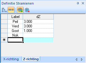 |
Grid lines in Z direction with relative dimensions |
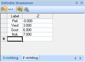 |
Grid lines Z direction with absolute dimensions |
2. Automatic generation of grid lines
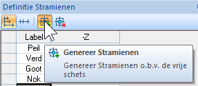 |
Check if the following button is activated. By default this button is on. |
Start by sketching the member model freely by clicking the start and end points of a member on the grid points. Make sure that nodes that must be above each other are also sketched above each other. Also make sure that nodes that need to be at the same height are also sketched next to each other.
During sketching, the member model is automatically provided with grid lines and dimension lines. When the free sketch is ready, the values in the 'Definition Grids' table can be adjusted. As with the manual entry of grids, it is also possible to choose between relative or absolute grid dimensions.
Grid
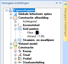 |
The grid is a grid with points in the graphical representation of the structure view. The grid is adjustable under the Display settings on the right side of the screen:
|
 |
Special functions:
|