MatrixFrame® version 5.5 SP5 - Release notes
Processed in version 5.5 (July 2021):
Bug fixes:
MatrixTools® Fire protection and MatrixFrame® steel check:
- If there was an uncoated steel section where not all sides were heated, both the profile factor and the shadow effect were adjusted in the calculation. This was not correct. The shadow effect should not be adjusted with an uncoated profile. The consequence of this was that in these cases the calculated time for the fire resistance turned out to be too favourable.
End release note v5.5-SP5
MatrixFrame® version 5.5 SP4 - Release notes
Processed in version 5.5 (April 2021):
New:
FEM:
- In a large model with many piles, the number of sub regions was exceeded. This has now been increased from 280 to 380.
Bug fixes:
MatrixFrame® General:
- It was incorrectly possible to enable the influence lines in the student version, in the advanced calculation dialog.
Loads generator NEN-EN:
- In case of rainwater accumulation of a horizontal beam, with slope and camber, the drainage was incorrectly calculated to 2 sides and then placed on the construction only on 1 side. Now an extra check is performed on the specified nodes at the position of the discharge.
Steel check:
- Occasionally not all lateral buckling supports were processed correctly, this was depending on the moments diagram. This made the UC larger than in the previous version.
1D Beam:
- When opening a model with large concentrated loads, the setting for shear force topping was not processed correctly.
2.5D Frame:
- In 2.5D Frame, the local and global deflections in y' were not displayed.
2D Grillage:
- In a large model with long beams, with many cuts in the concrete check, changes in the column for totall shear force was extremely slow.
MatrixTools Geo:
- After activating "Digging" and switching it off again, calculation was still done with the filled in digging parameter.
End release note v5.5-SP4
MatrixFrame® version 5.5 SP3 - Release notes
Processed in version 5.5 (March 2021):
New:
MatrixFloor®:
- In the settings for concrete an option has been added "Use top basic for thin slabs (<251 mm).
- It is now also possible to calculate kg/m2 for strips with different thicknesses.
Steel check:
- If several cross-section classes existed in a member, for example 1 and 3, the highest class was used in the compression and bending formulas 6.61 and 6.62.
This meant that with class 3 the elastic values were used and not the plastic ones. Now, per part of the beam, the check is carried out for each part with the cross-section class and forces applicable to that part. - If the lateral buckling control had tension in the flange, the tooltip of the UC showed "Lateral buckling N/A no bending" and the stability tab printed M; Ed = 0.00 for lateral buckling. This has now been adjusted to a message "Lateral buckling N/A flange under tension". The M; Ed is now simply displayed at stability.
MatrixTools®:
- In the module "Weld", "Static determed" was checked by default in a new installation, this has now been changed to "Static indetermed".
Bug fixes:
MatrixFrame® General:
- When exporting from MatrixFrame® to IFC, the sections were not always assigned to the members.
- Export IFC for Revit has been adapted to the newer Revit versions.
- Occasionally when opening a file by double clicking in the explorer, the start-up screen of MatrixFrame® became visible and then disappeared again without notification. Restarting again caused an "Out of memory" message.
- Self-entered material names were not read correctly when opening the model.
- In a model with a high Yr value for the support, this was no longer displayed correctly when opened.
- Import and export IFC for Advanced Steel no longer worked with the latest versions.
Module has been adapted to the current notification style and models can therefore be exchanged again.
Reports:
- When printing "JC Compressed" in 2D Frame of a group, not all loads were printed. As a result, empty load tables were shown.
Loads generator NEN-EN:
- For rainwater accumulation on a beam, for example with a length of 15.00m and a specified camber, the entire water surface was calculated for the left and right side instead of half.
MatrixFloor®:
- The generated non-structural load was not automatically set to end distance "L" like other generated loads.
- The deflection check did not calculate with 2 * L for an cantilever.
- The length of the top reinforcement was not correctly taken from the finished reinforcement.
- In the shear capacity of the concrete, the tensile force due to temperature load was taken into account, while in the concrete settings the option "Ignore normal force for reinforcement calculation" was set to yes.
- Occasionally the support reactions were not or incorrectly displayed on the screen and in the report. The other results such as shear forces and moments were correct.
- With a prestressed floor, with extra reinforcement at the top and bottom, it was not printed in the report.
- The concrete setting "Crack Management" did not work correctly when it was turned off.
Concrete check:
- The correct dimension for the width was not always determined during the check for "Brand". Incidentally, a too high reduction was made.
- The check for "Fire" now checks for the time based on the dimensions, so that these are available in the fire graphs.
- In a deep beam situation in combination with a concentrated load it was wrongly possible to top off the shear force.
- When topping of the shear force, the wrong position was taken if the left and right distance overlapped.
- The accidental combination was not included in the concrete calculation. A workaround in this version is now to activate the fire control with a time of 0 minutes.
- Incorrect gamma factors were used in the fire resistance calculation of a concrete column. As a result, more reinforcement was calculated than needed.
Steel check:
- For a combined construction part, with parametric tapered I sections, the correct equivalent sectiuon was not determined for the mirrored construction part. This created a higher UC for this part.
- After performing a GNL analysis, and checking the steel checks for lateral buckling and buckling, these were turned off again after changing a section, and had to be checked again.
Steel Joint connections:
- When calculating a stability connection, the wrong gamma was used to determine the "V;eff,2,Rd" for tearing out the bolt group. This reduced the design resistance.
- With a knee joint with tension plate, the control for bolt shear was not reflected in the output. The table "Tension plate in bending" has now been added for this purpose.
- For a beam-beam connection, the angle was drawn at 90 ° in the drawing if it was less than 90 °.
2D Frame:
- Occasionally a message was given for a model with an NL-bar connection "during a GNL calculation: WARNING: Instability.
- The import of a dxf, which was drawn in AutoCad in [Top] [2D Wireframe], no longer worked. Model was imported as a 3D model.
2D Grillage:
- In the report, the "Images for load cases", for an imposed load with generated fields, were not correctly displayed. An empty load case was shown and then only the sub load cases. An image with all the imposed loads was missing.
3D Frame:
- Occasionally a "Distributed area load", which included many non-load-supported beams, was not distributed correctly everywhere. Now there is always a warning when something like this occurs.
- When using "Distributed area load", on structures where there were several beamsin the plane that did not act as support, the loads were not always correctly processed in the "P-load decomposition. As a result, the total of the loads was not always equal to the specified plane There is now also a check built in which compares the generated loads with the specified plane If this is not correct, the load will be colored red in the table.
- In the section table it was not possible to change the angle of a strip (for example R120x15).
2D Grillage/Plate:
- With the mobile load generator it was not possible to enter the "Ldr. Offset".
- The reinforcement legend was not correctly displayed in the FEM results.
FEM:
- When opening a model, in which the default reinforcement for FEM was set to "FeB400HWL", "B500B" was filled in after recalculation and starting the reinforcement dialog.
- Occasionally, plates and walls were not correctly imported via IFC.
MatrixTools®:
- After closing and restarting MatrixTools®, all project data was deleted instead of just the part.
- Module "Punch":
- Crashed occasionally. Problem was caused when no punching reinforcement was needed.
- Strange results were calculated for a circular load area if a value of 0 was entered in the "Length of loading area C2".
- At corner and edge columns bent bars were drawn on top of each other. Because of this the same number of bars was not seen as in the table.
- Incidentally, the stirrups at a center column were not shown symmetrically in the drawing.
- In the module "Advanced punch" the "Total reinforcement" was incorrectly displayed at an edge column.
- For the module "M-N-Kappa diagram", the normal force as a result of prestressing was not reported in the report.
- In the module "Column calculation + Fire" it was incorrectly possible to enter a required time of more than 120 minutes.
MatrixTools® Geo:
- In the report, the ground level was not printed correctly in the image of the "Compression pile with friction pile".
- When using a "Micro pile system" the program crashed when printing and / or clicking the NL diagram. The settlement values for limit states 1B and 2 were also not calculated. The problem was that no modulus of E was defined for the micropile. Now the modulus of elasticity of steel for micropiles has been added.
End release note v5.5-SP3
MatrixFrame® version 5.5 SP2 - Release notes
Processed in version 5.5 (December 2020):
New:
MatrixFrame® General:
- The names of the tabs in Excel have been changed. This means that horizontal scrolling is no longer necessary.
- In an FNL calculation, the creep factor had to be entered in the "Advanced calculation" dialog. This was then used for all sections. It is now possible to enter a creep factor for each concrete section so that with an FNL calculation each section has its own creep factor.
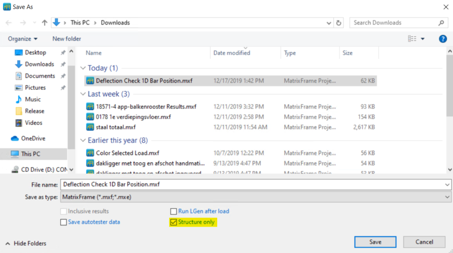
- It is no longer possible to check both options, "Inclusive results" and "Structure only" at the same time under "Save as ....". If "Inclusive results" is checked, the option "Structure only" is no longer editable.
MatrixFloor®:
- In the display options in the settings, for the project explorer, extra options have been added to hide columns. If the column is hidden, it will not be printed in the report either.
- It is now possible to have the length determined based on the field lengths entered. This choice can be made when starting a new project.
- The deflection design procedure, if no reinforcement has been defined, has been improved.
- The rib plate has been added to the floor types.
- For a rib floor a default setting has been added "Design 2 bars per rib."
- In the concrete output the "h-ds" value for floor plate has been replaced by "ds".
- In the title of the table "Connecting reinforcement", information about the lattice girder used has been added.
- Report item added with Load generator options.
- If the montage phase is decisive for the concrete, this is displayed graphically under "End of lifetime" and in the tables in the tooltip.
Steel check:
- With a large 3D model with hundreds of load combinations, the steel check could be very slow because * .tmp files are created first. This has to do with the setting in "options / miscallenous" "Minimal count of result members to start cash:". This is set to 100000 by default and if this is increased to, for example, 1000000, no * .tmp files will be created anymore, so that the steel check is started immediately.
MatrixTools®:
- In the module "Punching calculation advanced" the calculation and drawing of tangential reinforcement has been completely renewed. A column has also been added in the results tab for the number of cuts to make it clearer how the distribution is per periphery. A button has also been added to the drawing that shows the peripheries to make checking easier.
MatrixTools® Geo:
- When using multiple CPT diagrams, the calculation was started immediately when 1 was checked or unchecked. As a result, checking or unchecking was not easy to arrange. There is now a timer built in that is set at 1.5 sec. state so that multiple CPT diagrams can be checked or unchecked.
- If no soil layers were generated on a CPT diagram, an "Rb;d" was incorrectly calculated in the "Average results". Now the selected diagrams are displayed in red and the tooltip reports that no soil layers have been defined.
- In the report items "Compression pile Summary" and "Compression pile Summary per CPT", the Ksi; 3 and Ksi; 4 values are now also printed. The normative is printed in bold.
Bug fixes:
MatrixFrame® General:
- If the interface was German, it was not possible to define a mass combination.
- The moments were not shown in the support reactions tab of an Excel.
- Incidentally, it was not possible to join inclined beams, which were in one line.
- The NL supports were not detected in advanced calculations.
- In the FNL calculation, the chosen position and the diagrams were not visualized correctly.
- When inserting a project in 3D, only the nodes were shown and the members were not present.
- Incidentally, a 3D model turned out to have become corrupt when opened. All nodes and grids were rounded to meters. This resulted in grid sizes of 0.000 and the construction was no longer correct. This problem seems to have arisen while saving, but we have not been able to reproduce it. Extra controls are built in to prevent this behavior.
- Occasionally a model from 5.4 could not be opened in 5.5.
Reports:
- MatrixFrame® exited without warning, if the print preview was still open, while trying to close the "Report Settings" dialog with the cross.
- In the image of the reinforcement, bars were shown in red if they were selected on the screen.
Loads generator NEN-EN:
- With a small system length of 1,000m or less, an error occurred in the calculation of the CsCd factor, so that a value of 0 was entered. In loads calculations, the formula in the calculation cell was colored red with an error message in the tooltip. Problem was related to the N1x and Delta values to be used.
MatrixFloor®:
- MatrixFloor crashed when navigating too quickly with the "Tab" through the "Projektbrowser".
- The calculation of kg / m2 has been adjusted and broken down into parts. The reporting has also been adjusted and a report is now made per strip with kg / m2 and 1 total table with kg / m2 for each part.
- If the imposed load category was changed from floor to inaccessible roof, and for the permanent load the finishing was put on roofs, no permanent finishing was generated.
- Fixed problem with reinforcement calculation for section change in a field and for openings.
- With a section change in combination with a support close by, the reinforcement texts were printed together. This has now been resolved through changes in alignment and conflict detection.
- During the montage phase, only the plate thickness was calculated for a floor plate.
- With design on deflection based on "mm2", this was not always correctly processed in the As provided, so the As provided showed a lower number than the As required.
2D Frame:
- At 2.5D, the angle setting did not work in the section definition window. This could now only be entered in the table.
2D Grillage:
- When advanced calculations with shear force correction, strange peaks appeared in the shear force line at the location of a support that also had a concentrated load.
- Incidentally, only beam 1 was printed in the report of "Concrete bar(compr.)"
- For a grillage, in which walls were used with a release connection that was free in "Vz" or had a spring value of 1, strange jumps were drawn in the node displacements. The results were otherwise correct.
2D Grillage/Plate:
- If concrete beams were coupled, for example with a slab with edge beams, these were seen as 1 structual member and not as separate structual members.
- In the "Report Settings" only the items and images of the plate were shown.
FEM:
- Occasionally the mesh gave an error while the geometry check showed no problems.
This could be caused by an inaccuracy in a vertex point that, for example, was not in the same place on the 7th digit after the decimal point as another vertex. This can be solved by having grids generated. Usually these problems occur after an import of a "DXF" file. - In case of the single-core processor, no correct message was given if the maximum number of mesh elements of 32000 was exceeded.
- Occasionally, the mesh gave an error message when the last point from a polyline support overlapped the line between 2 other points of the same support.
- With 2-D Grillage / Plate, polyline supports were not processed correctly. As a result, supports disappeared in the results.
- In the 2-D Grillage / Plate module, the FEM dxf import did not work.
- The modeled connectivity was not graphically selected if you selected it in the table.
- In the picture settings the "Connectivity" was missing.
- When opening a model made in 5.4, a negative P-load was not correctly adopted. This resulted in an error message "Wrong load value". Redefining the load solved the problem.
- Occasionally, when generating fields for an imposed load, parts of the plate were left unloaded. After opening an incorrect model, the load must be removed and re-created.
Concrete check:
- The deflection was not calculated if the beam was between 45 ° and 135 °.
- With 1D beams, the stirrups and bottom reinforcement were occasionally not correctly placed for a beam with different cross sections.
- In the case of a beam, which consists of several sections and is therefore divided into, for example, 1a and 1b, the "lov" for the deep beam test was incorrectly determined if it continued in both parts.
- In bar placement in 2D-Grillage, 2 additional bars, which lay in 2 fields with an overlap, were incidentally not combined into 1 bar.
- In bar placement in 2D-Grillage, an additional bar, which lay over 2 fields, was occasionally displayed in duplicate.
Steel check:
- With a model in "2.5D-Frame", the deflection was only tested on Y 'and not on Z' and Z".
Steel Joint connections:
- With a column-beam connection, where the column was a 90 ° rotated UNP, it was shown incorrectly in the drawing at the front view and section A-A.
Timber check:
- When setting the timber control definitions of a large 3D model, every change took an extremely long time. The problem was that with every change the construction parts were redetected.
- For members combined to 1 structual member, the "Unity Check member color" was occasionally not drawn in the correct position.
MatrixTools®:
- With various modules, including, for example, timber beams, the document info was no longer printed at the top of the report.
- Point-supported floor with a column plate:
- A moment that was too high was calculated on the transition from the slab to the floor.
- Additional reinforcement in addition to the column plate is now calculated if the width of the column plate is smaller than the reinforcement track.
- The total height was incorrectly calculated for the strip.
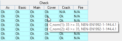
- With the concrete module "Column calculation + Fire" it was not always indicated that the Cnom. does not meet. Also, only 1 control was shown in the tooltip. Now both checks, so for the stirrup reinforcement as well as for the main reinforcement, are shown.
- In the concrete module "M-N-Kappa diagram" the prestressing force was incorrectly not included for the Nc; Ed. The tooltip next to the cell for NcEd now shows the total force including the prestressing force.
- With the concrete module "M-N-kappa diagram", when copying the module, the coverages were not correctly copied but set to a default generated value.
- In the concrete module "Punching calculation advanced", when applying tangential and changing the diameter, this diameter was not correctly included in the control for Asw; prov. and Rk min.
- In the masonry module "Wall calculation" the text "The support meets the requirements" was occasionally incorrectly displayed while a UC of 999.0 was displayed in red.
MatrixTools® Geo:
- On a spread foundation, the report crashed if the end of the construction depth was deeper than the generated soil layers.
- With the building type, the option "Not Stiff Partial" has been removed because this option is unnecessary. The calculation was performed as "Not-Stiff".
- In the output, "Rb;cal;max;rep" and "Rs;cal;max;rep" were incorrectly printed instead of "Rb;cal;max;d" and "Rs;cal;max;d" printed in report summary per CPT diagram. The values were correct.
- In the calculation of a spread foundation, the "L" was not included in the calculation if "strip width B; min" and "B; max" had the same value. In that case, a square column foundation with the value of the strip width was always calculated.
End release note v5.5-SP2
MatrixFrame® version 5.5 SP1 - Release notes
Processed in version 5.5 (March 2020):
New:
MatrixFloor®:
- If the section shows reinforcement type "None", a proposal is now generated based on the default settings.
- The As;req is now also displayed graphically if no reinforcement has been entered or generated
Steel check:
- For the EN, Mcr for lateral buckling is now determined using the NEN-EN method.
Bug fixes:
MatrixFrame® General:
- USB key was no longer recognized after installation 5.5. This problem occurs on Windows 10, if the key was in the usb port during the installation. This can be solved by installing without a key and then restarting the PC.
- The use of Excel tables in Word did not work if the "MatrixFrame® 5.5 Excel Add in" was activated. This issue has now been resolved.
- In the structural member view, the loads were not shown if the envelope was activated. Also, the "Structural Member Layers" tab in the "Visibility properties" disappeared if you went to the member forces.
- If the "Envelope" button was activated, it was no longer possible to select the load cases in the list.
- The self-weight was not correctly displayed when applying a tapered profile. After saving the model and re-opening it was correct.
- For the results of the load cases, only the numbers were shown in the selection list and no longer the descriptions.
- For the folders in options, the "Project path" setting had disappeared. This setting does the same as the "Library Path" so these are now merged into 1 as "Project path".
- In the combination generator dialog, the check box "Filter combinations by envelopes" had disappeared.
Reports:
- The default "Colors per load case type" were not set correctly. As a result, it permanently was printed in light yellow and snow in white.
- The images of the "Member View Envelope" were not displayed correctly.
- When opening a project, the set headers and footers were not read correctly. As a result, these were set to default values.
- The steel check was not printed the 1st time when generating a preview.
Loads generator NEN-EN:
- With a Telecom pole, which consisted of different sections, incidentally the wind load was not generated on the pole.
- With the generation of rainwater in "3D system, 1 field", the supports were wrongly fixed for "Xr". As a result, the girder that was connected to the support was also considered to be fixed.
2D Frame:
- Loads outside the beam, with a value of 0, caused incorrect results with a value of "-nan (ind)" when using the "Multi-core processor".
2D Grillage:
- Occasionally a report of incorrectly entered loads appeared after opening a model from MatrixFrame® 5.4.
- Opening a model from 5.4 caused a crash in MatrixFrame® when saving. Temporary solution was to have the concrete data removed in the menu.
- When assigning the deflection type, these were not set for beams that had releases.
- When importing an "RTF", incorrect loads are now removed. Also the tables with extra table headers are now processed correctly.
3D Frame:
- When using selections and work planes, the support reactions were not shown.
- When using selections and work planes, the loads were no longer filtered in the tables.
- When using MatrixTools® "Cross-section calculation" or "Column calculation", the forces were set in the wrong direction if the section was rotated 90 °.
- When performing a Dynamic analysis of a lattice mast, MatrixFrame® froze.
FEM:
- When importing a DXF, the geometry and loads were incorrectly processed.
- When viewing generated load fields, MatrixFrame® was closed without warning.
- Occasionally MatrixFrame® crashed when assigning reinforcement.
- Occasionally MatrixFrame® was closed without warning at the end of the calculation.
Concrete check:
- In the "Concrete settings" in the "Cover" tab, checking "Uneven" had no effect.
- It was no longer possible to adjust the elasticity when using concrete.
Steel check:
- When checking for fire resistance, for the "Beam" static system, a lateral buckling check was wrongly done while the lateral buckling was turned off.
- The UC Check member color was not always correctly displayed in an assembled structural member. The first UC was shown and not the maximum, now the maximum is always shown.
Steel Joint connections:
- The bolt distances were not checked for a beam over a column.
- The "Column web and flange under pressure" check apparently did not take into account the compression and tension plate. This happened with a beam that lays on top of the column. The check is made according to NEN-EN 1993-1-1 + C2: 2011 / NB: 2011 # 6.5.3.2, # 6.5.3.3 and # 6.5.3.4. This check does not have to be done with tension and compression plates are used. However, the plate will not be included as a stiffener if it is in class 4 or not in the compression zone. This information will now be visible in the output.
MatrixTools®:
- In the NEN-EN, the button in "CT Concrete Punching Calculation" was not activated. The calculation could be performed by opening a model from 5.4.
- In the concrete module "Column calculation + fire", the λ for the fire combination was not determined with the reduced dimensions.
- When starting up a module in timber beams for the first time, the results grid remained gray. Closing and opening the toolbox again resolves the issue.
- When lime mortar was used a compressive strength "f'm" could be entered in the masonry modules. This had no influence on the calculation and is now turned off when using lime mortar.
- In the masonry module, a UC of 0 was wrongly displayed if a column or wall ran out of the graph of NEN-EN1996-1-1 annex G "Figure G.1". The final conclusion was correctly displayed. "The requirements are not met". Now a UC = 999 will always be displayed.
MatrixTools® Geo:
- For a compression pile calculation with the pile type "Shaped in soil with CFA, screwed, the" Limit qc; 3avg. "of 2.0" was not corrected for the last soil layer. As a result, calculations were made with a higher qc; 3avg.
End release note v5.5-SP1
MatrixFrame® version 5.5 - Release notes
Processed in version 5.5 (January 2020):
New:
MatrixFrame® & Excel:
In the previous version of MatrixFrame®, the exchange of calculation models with Revit and Tekla was introduced. A link with Excel has been made in this version. Herein there are functions for the modeller / constructor to define and manage calculation models within the Excel environment, to perform calculations whether or not underwater, so without MatrixFrame® on the screen, to monitor the progress of the (calculation) tasks and view the calculation results and use them from the generated Excel tabs. (This is an extension module)
During the installation, a dialog box appears when Excel is on the PC.
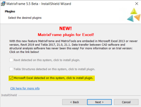
When starting Excel, the plug-in will be installed and a menu item "Matrix Software" will be visible.
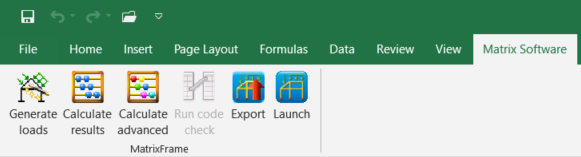
The new options listed:
- “Generate loads” generates loads with the load generator.
- “Calculate Results” start the calculation without MatrixFrame® appearing on the screen and put the results back in the different tabs.
![]()
- "Calculate advanced" starts the dialog where the tension- or compression elements are displayed and other advanced settings can be made.
- “Export” will save a * .mxml which can then be opened in MatrixFrame®. This file contains the geometry and the user-entered loads and load combinations.
- “Launch” MatrixFrame® will start with the data entered by the user.
The different tabs briefly explained:
- Input: User settings can be defined here. For example, geometry and load settings, or load and combination generator. This step must be performed if the content of the underlying tabs is to be generated automatically.
- MxProjectData: Here the project type is set and the NEN-EN standards are also defined.
- MxGridlines: Here you see an overview of the grid lines that can be read from the input.
- MxGeometry: Here the members and nodes can be defined with boundary conditions.
- MxSections: Here the sections are defined with boundary conditions.
- MxSupports: Here the supports are defined which are used in MxGeometry.
- MxReleases: Releases are defined here which are used in MxGeometry.
- MxRigidLinks: Rigid links are defined here which are used in MxGeometry.
- MxElasticFoundation: Here elastic foundations are defined which are used in MxGeometry.
- MxLoadsGenerator: This module is currently being developed.
- MxLoads: Here you can define the loads and after using the load generator the generated loads will be shown here.
- MxLoadcases: Here you can define the load cases and after using the load generator the generated load cases will be shown here.
- MxLoadCombs: Here you can define the load combinations and after using the load generator the generated combinations will be shown here.
- MxSteelCheck: This module is currently being developed.
- MxTimberCheck: This module is currently being developed.
All tables in the tabs are dynamic so new rows can be added.
MatrixFloor®
A new program has been developed for calculating floor plates and hollow core slab floors: “MatrixFloor”. (This is an extension module)
This will be further expanded with rib cassettes and combination floors and beam bottoms in a next version. (This is an extension module)
It is also possible to link these with drawing packages such as IC-Prefab.
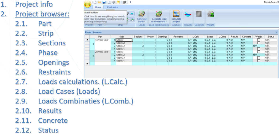
In "MatrixFloor" it is possible to enter several parts (floors) in 1 project and several strips can be calculated per part.
The layout is:
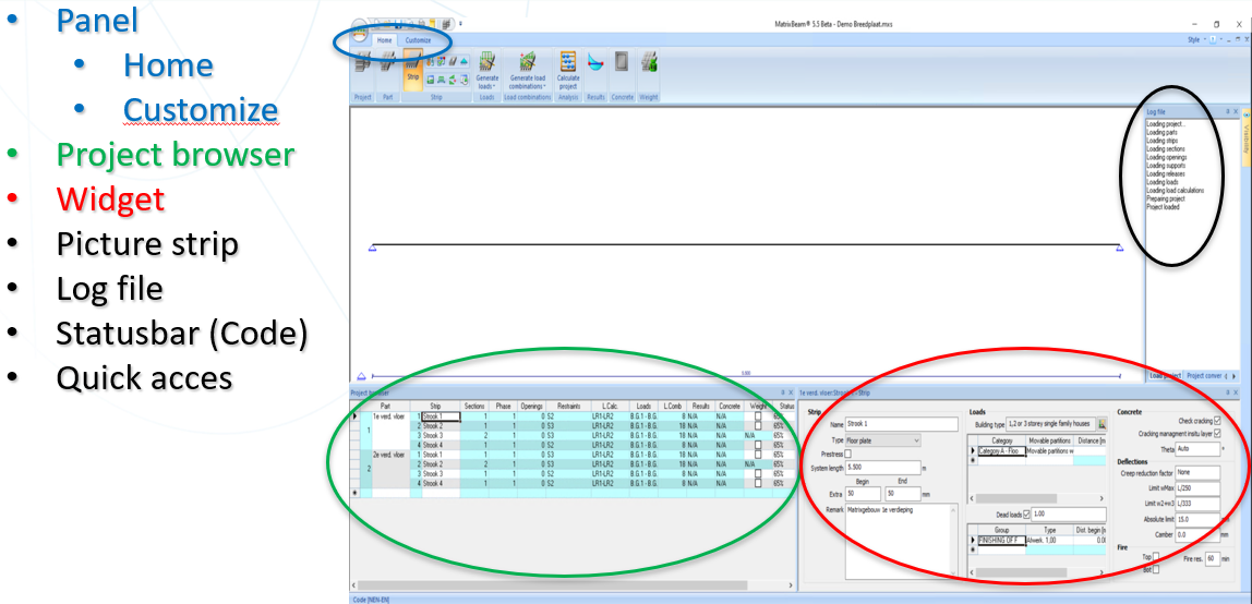
The philosophy is:
- 1 file (* .mxs) contains an entire project.
- For each chosen option within the project, the required Widget is displayed with the required information.
- This project can consist of several parts (1st floor, 2nd floor ... ..).
- This part can consist of several strips.
- All required geometry and load data can then be defined per strip.
- Here the results and concrete calculation can also be viewed.
- A status can be assigned to each strip.
The workflow short explanation:
Navigation:
- Navigation is possible in 3 ways:
- With the mouse via the buttons in the toolbar (for changing a project)
- With the mouse by clicking in a cell in the Project manager
- Use the keyboard with the [Tab] key to jump through the Project Manager from cell to cell (so works as an input wizard)
- Use the keyboard with the [Ctrl] + [Tab] to switch between the Project Manager and the related Widget
- When a next strip is activated, all data from the last strip is automatically copied.
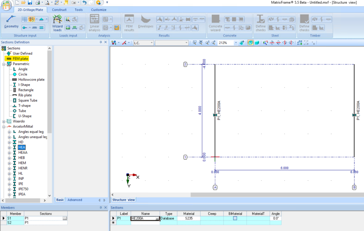
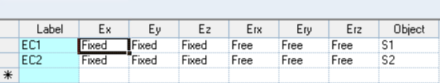
2D Grillage/Plate:
- New project type added: “2D Grillage / Plate”. (This is an extension module).
- After beams have been defined, you can define the plate in the “Section Definition” by entering the plate data and activating the “Create region” button.
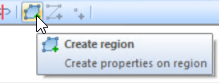
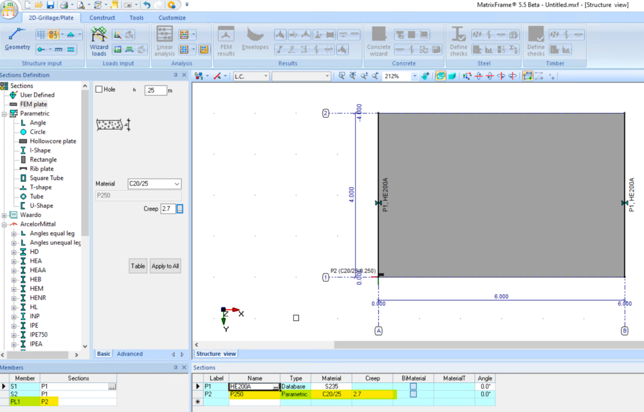
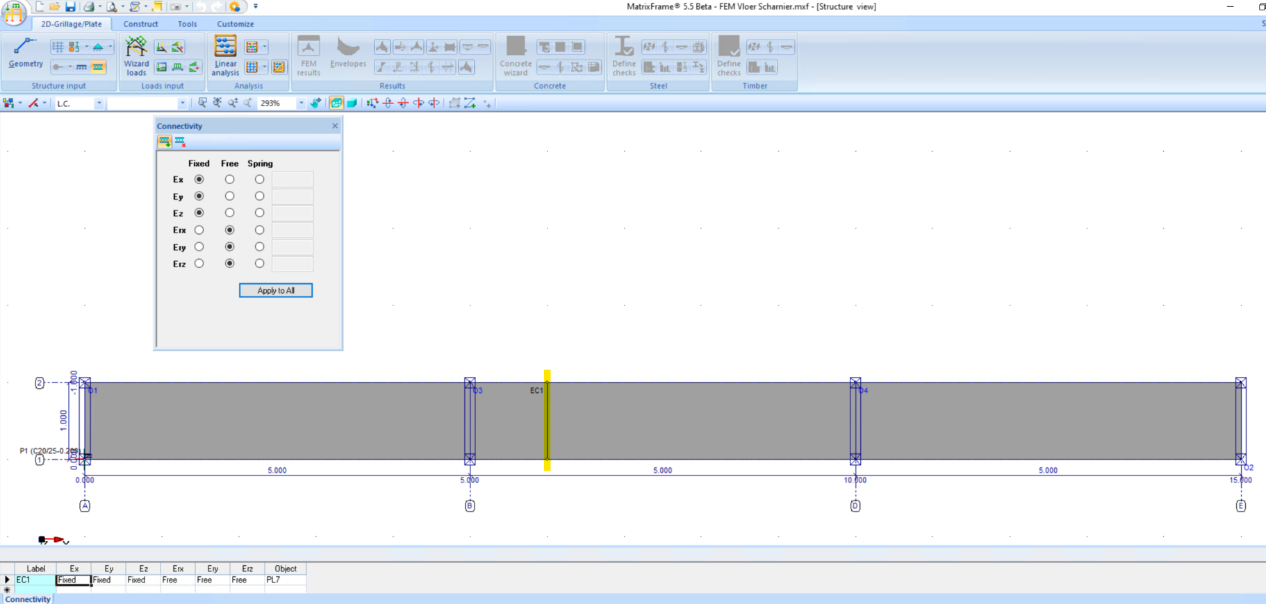
- The connection between the plate and the beam can be set with the “Connectivity” button, the connection is completely fixed in all directions by default.
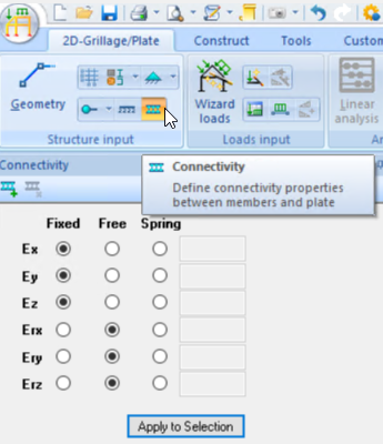
- The connection defined above is that the plate is rotation free on the beam.
- After placing the supports, under the beams and or plates, loads can be placed and the combinations generated.
- The calculation can then be performed.
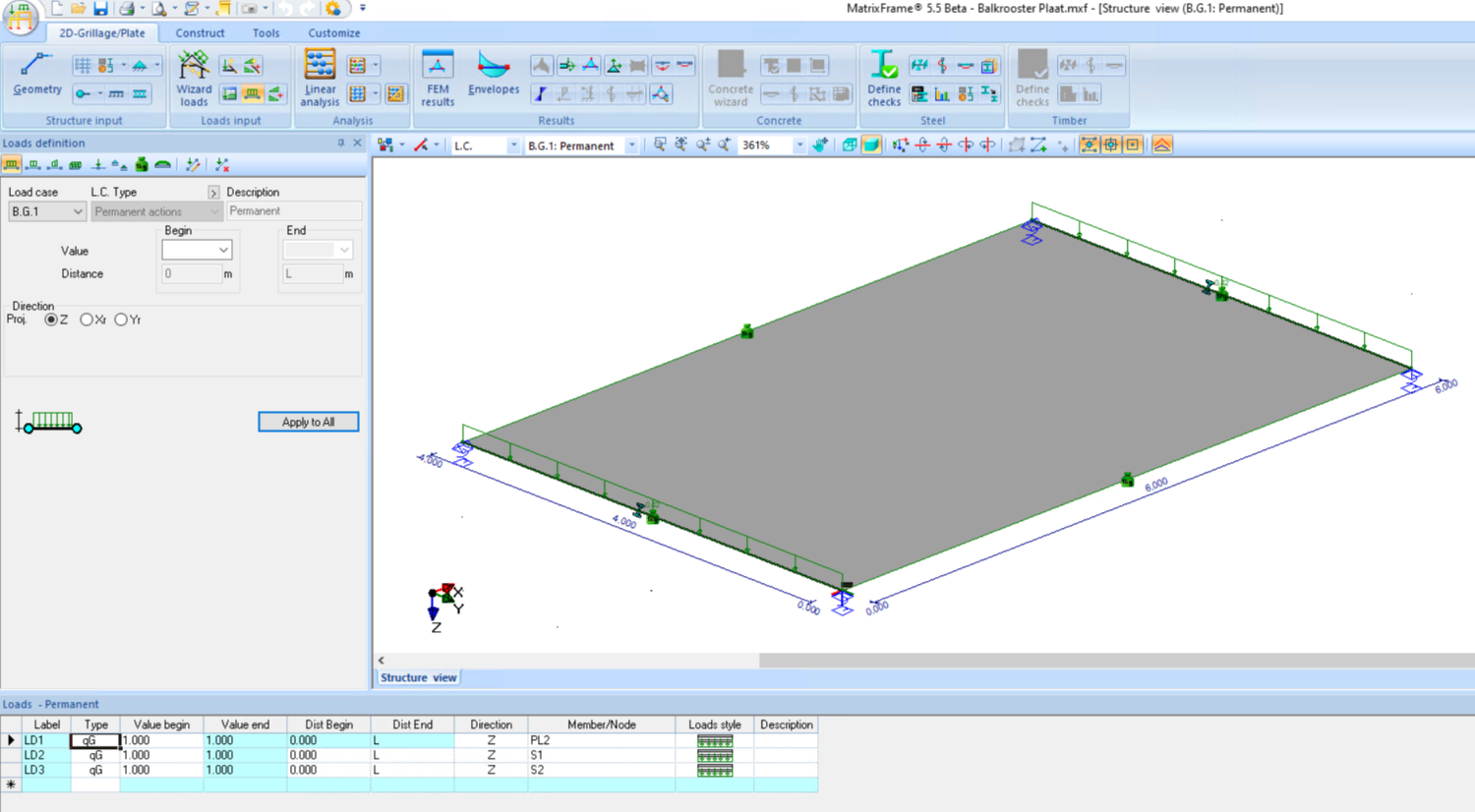
- The results of the beams can now be viewed.
- The results of the plate can be viewed separately.
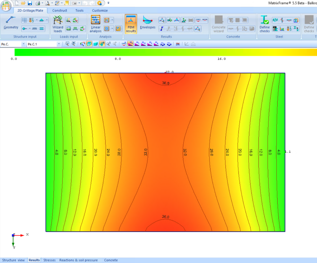
- After this, the standard code checks can be done for the beams and the plate.
- The "Connectivity" can also be used to make a rotation free release in a plate. This is done by defining a polyline.

Matrix PT:
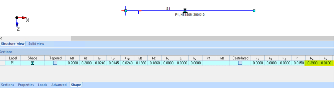
The "Matrix PT" has been renewed. It is now possible to adjust values generated in your own section group where necessary.
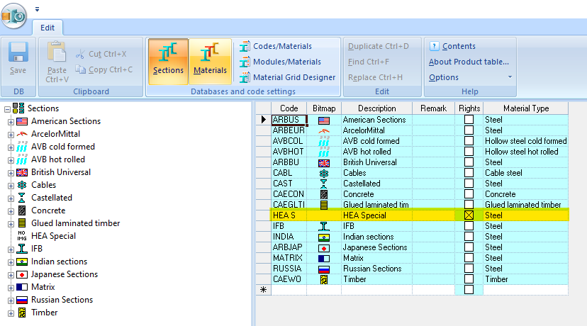
- After creating, for example, the HEA Special section group, you can create subgroups on it.
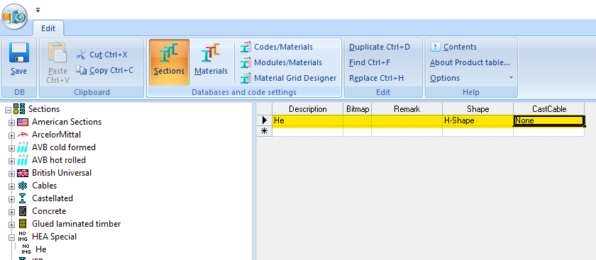
- The sections are then created by defining a name and the shape & dimensions.
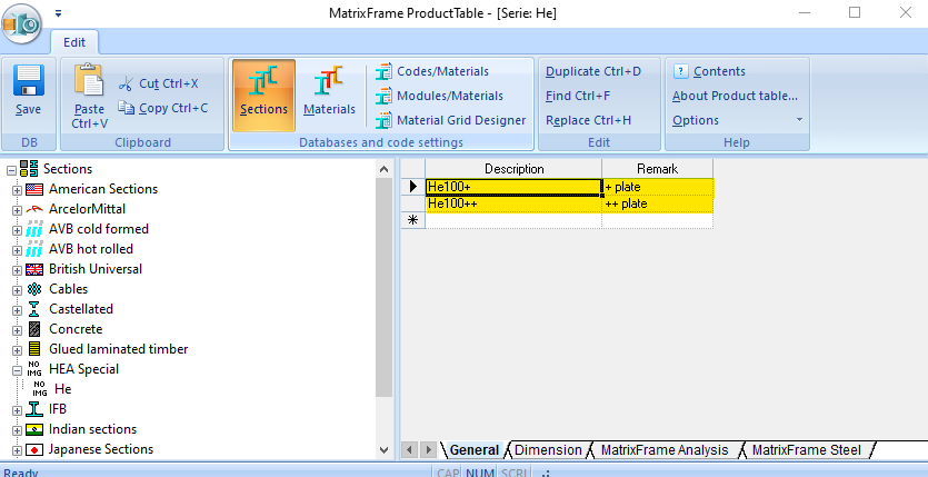
- If the section is validated, the associated values will be generated and displayed in blue. These values can then be adjusted and will then be displayed in black.
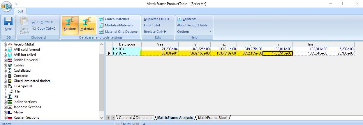
- After saving the database, the sections created here will be available in MatrixFrame® and the standard checks will also be done.
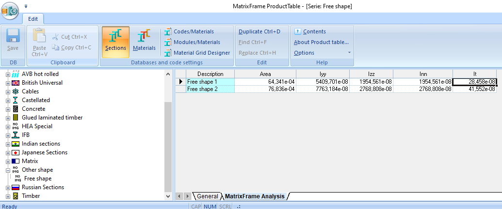
- In case that the section form is not supported (free form), and therefore cannot be validated, the user can enter the required values with which the calculation can then be performed. Code related checks are then not possible.
MatrixFrame® General:
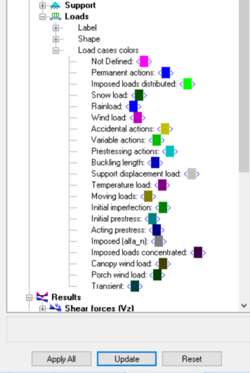
- It is now possible to set a colour per load case type.
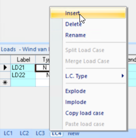
- It is now possible to insert a load case between already defined load cases. Click with the right mouse button on the tab of the load case where you want to insert the new load case and choose insert.
- It is now possible to copy area loads. This can be done by selecting the entire line and then copying. All vertices, supports and P-load compositions are then copied.
- Various adjustments have been made to support high resolution screens. As a result, the user has to make fewer changes to his user profile.
- The size of the letter fonts is now automatically adjusted when using a high resolution screen.
- When saving as * .mxf or * .mxml it is now possible to only save the structure data. Results, material-related checks and user profiles are then not included.
- When exporting to * .mxml, the descriptions of the structural parts are now also stored for concrete.
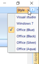
- It is now possible to choose a Style for MatrixFrame® and MatrixTools®.
- Mobile load systems are now stored in the model.
- The calculation of the "It" for angular sections has been adjusted. This is now calculated with the Roark formula.
- The section table has been expanded with the width and thickness of the plate for IFB sections.
Reports:
- For the "Concrete definition", the "Grid lines and dimensions lines" layers have now been added to add layers, for example for supports. This makes it now also visible in the picture of the concrete bar position.
Loads generator NEN-EN:
- An option has been added to have the construction parts redetected.
- For the wind generation on Telecom poles, a tapered section is now also supported.
- When generating the wind on Telecom poles, the width of the section is now always used.
- If in the load generator for Telecom was zoomed in 3D, the nodes were no longer displayed. The layer now remains on or off during all steps of the load generator.
- With a flat roof, it is now also possible to generate snow abuting to taller construction works at both ends.
- With the "Rainwater accumulation" module, the positions of the drains are now detected at a predefined slope in the roof. With this, the correct rainwater load can be determined for each roof surface.
MatrixFloor®:
- Bar position has now also been implemented.
- The support reactions are now also graphically visible.
- For the hollowcore plate the prestressed steel is set to "Y1860" with a Sigma, pd of 100 for the upper strands and 1400 for the other strands.
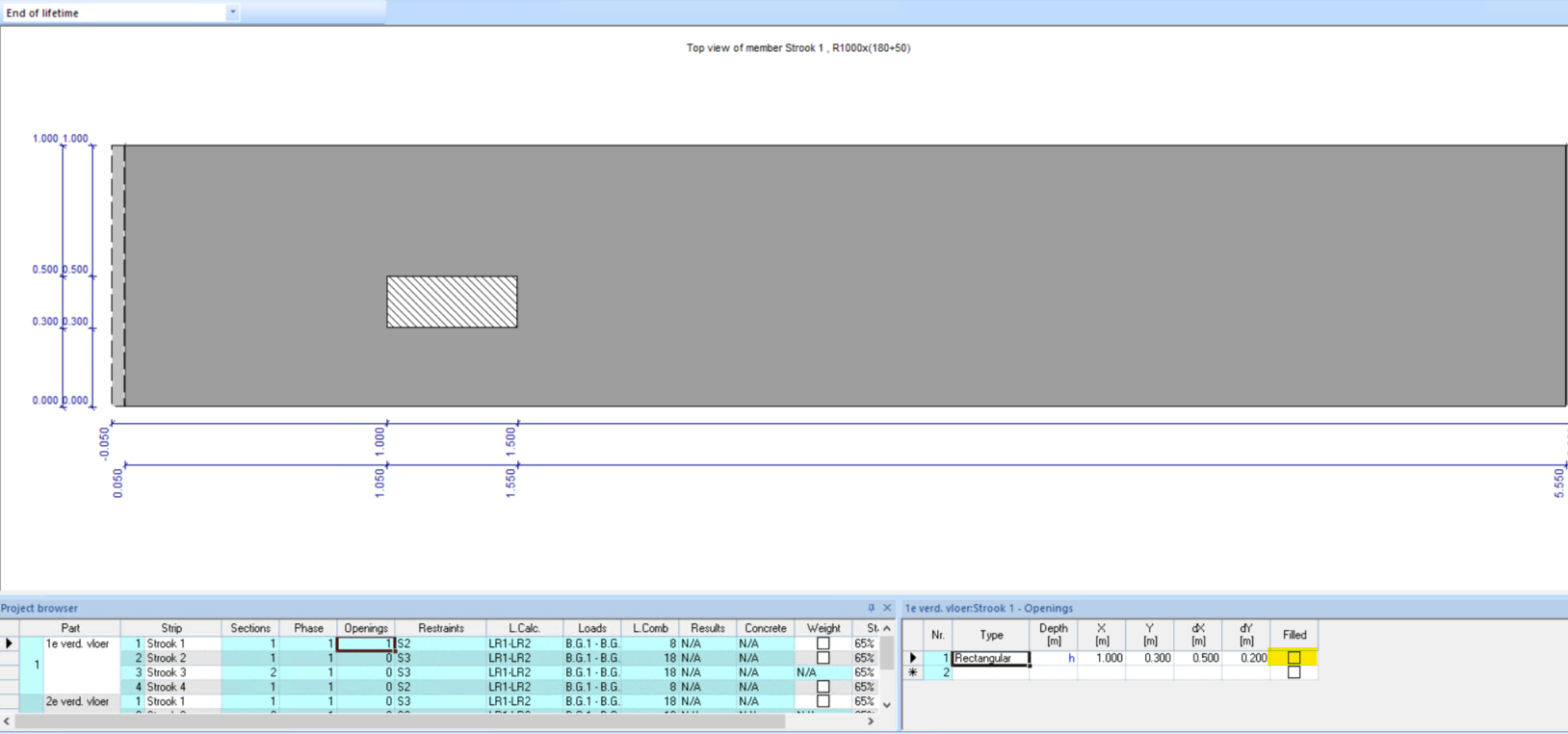
- For openings, the option "Filled" has been added. If this is on then there will be no reduction of the weight of the plate.
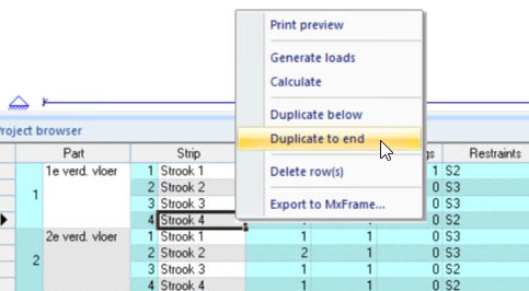
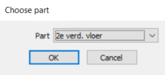
- It is now possible to copy a part (floor) or a strip from one part to another part. Select the cell with the part name or strip name and click on the right mouse button and choose "Duplicate to end" and choose part.
- It is now possible to choose tables and pictures or only tables or pictures.
- Mobile load generator has been added.
- When placing a support, the settings of the previous support are taken over.
- The images in the report are automatically synchronized with the images on the screen. If the user wants to change this, he can adjust this for reports using the "Layers" button.
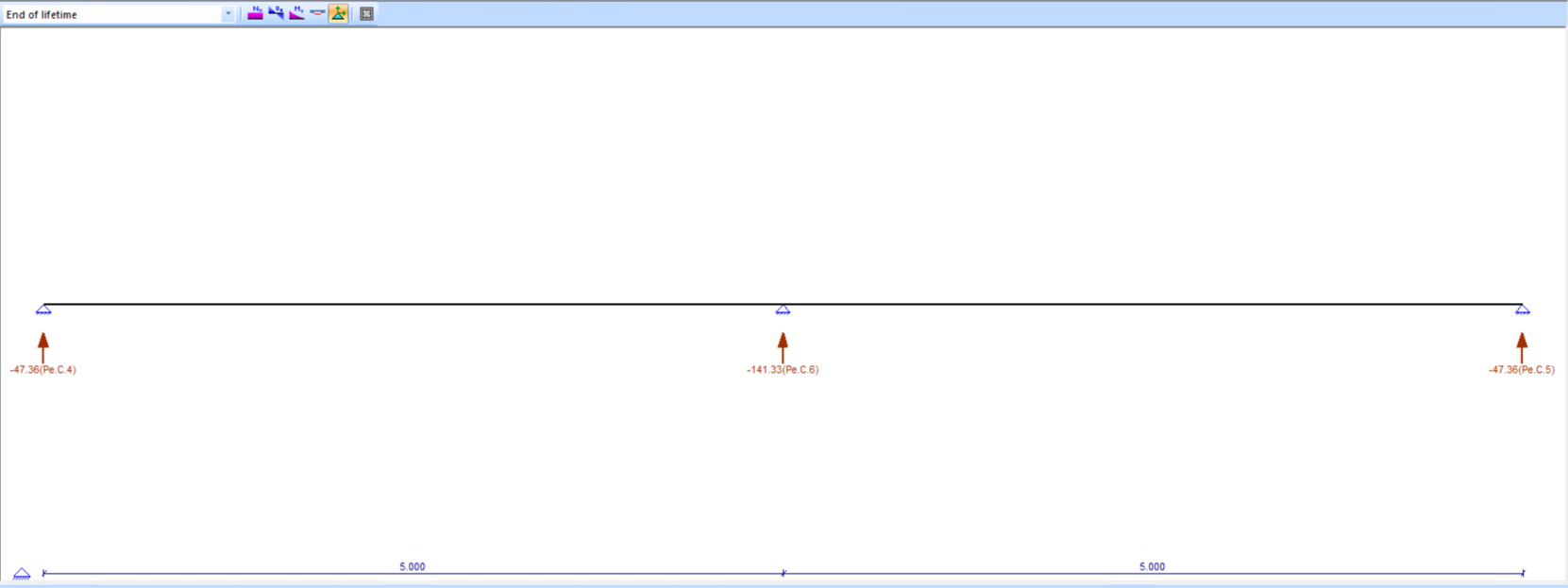
- Table with persistent and characteristic supports reactions has been added to the report. Reactions are also broken down into permanent and imposed.
- The recent sections in the "Section Definition" dialog are now displayed per project and no longer per strip.
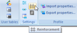
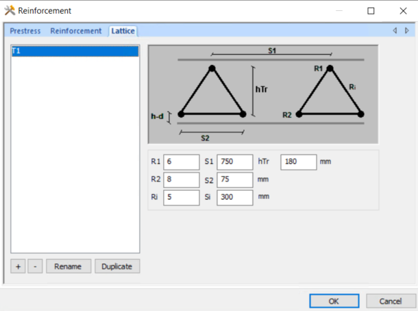
- It is now possible to define standard lattice girders at the reinforcement settings.
- It is now possible to adjust the normative Psi factors.

- The "Description" column is also displayed in the report. With this, for example, a point load can be used to describe where it comes from. (Reaction from strip 3)
- It is now possible to set separately for each imposed load whether movable partitions should be included.
- If a support is placed at the beginning or end of the strip, the check box of the accidental clamping (Mpf) will be activated automatically.
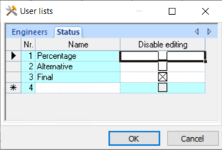
- You can now activate a check box at the user list in the "Status" tab to block editing of the strip.
- In the report, each strip starts on a new page.
- The time of the GGT is now used for the creep to determine the number of days.
- For phases, the time can be entered in both days and years.
1D Beam:
- The table for supports has been added for 1.5D. This allows the supports to be adjusted. The report has also been adjusted.
3D Frame:
- When generating the supporting beams, for a distributed area load, tension beams and compression beams are excluded.
- The grid line, with dimensions for the Z direction, is no longer displayed at the X = 0 and Y = 0 position but at X = 0 and the last Y grid line.
FEM:
- The "Connectivity" can also be used to make a rotation free release in a plate. This is done by defining a polyline.
- It is now possible to copy a load case including all vertices.
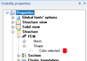
- In the "Visibility properties" a layer has been added for setting the "Color selected" of the structure.
- In the report, when printing "Load Cases (Incl. Pict.)" Now also the values of the loads are printed.
Concrete check:
- The module for bar positioning from the stirrups has been completely renewed.
- Stirrups are now only drawn where they are needed in a strip.
- The cover check has been expanded. The cover is now checked for the 1st and 2nd layer of reinforcement.
Steel Joint connections:
- At the base plate connection, the input for the anchors is extended. Now the "Total anchor length" is entered and the "Anchor length in the concrete".
- With a Bolted- splice connection, it is now also possible to use a haunch on top.
- With a welded stability connection, an additional check has been added for the shear force on the pipe wall.
MatrixTools®:
- In the steel "Cross calculation" module, the report has been expanded and depends on the combination of forces that exist.
- In the steel "Cross calculation" module, a tool tip has been added for if the UC is> 1 in the single check. If this is the case, the combined checks are no longer performed.
MatrixTools® Geo:
- Report "Compression Pile summary by CPT" has been expanded with the column "Fc; netto".
Bugfixes:
MatrixFrame® General:
- The height of the cold tube "KK250 / 150/10" was incorrect in the database. This was 0.22 instead of 0.25 and as a result the calculated section properties were lower than expected.
- Failure to display dialogues when working with fewer screens has been resolved.
- The calculation was not performed if an eccentricity was defined in X at a beam, on one side, that was greater than 0.5 * length.
Reports:
- Generating a report from a large grillage model with concrete beams was very slow when pictures of the reinforcement were printed. This has now been optimized, but you must first have activated the "Concrete bar position".
- When exporting to editable RTF, the UC colours and values were not always shown in the "Pic. Steel UC Chart".
- Occasionally an error message appeared on the report in the NEN of "Concrete cross section (detailed)".
- If a space in the name was used in a user-defined memo, the saved model could no longer be opened. An empty model was displayed.
- When printing a selection of a number of concrete beams, empty tables of all unselected beams were also shown.
Loads generator NEN-EN:
- When generating rainwater, on a flat beam, the slope and the camber were not correctly processed with a "3D system, Inner field". As a result, too much water was generated on the beam.
- With a portal with 2 columns of different length, with a slope modelled to 2 sides in the roof, water was only generated on 1 side.
MatrixFloor®:
- With the concrete bending, the limit values of "Wmax" and "W2 + W3" were exchanged.
- Scaling the height in side view was not in correct proportions.
- The roughness of the surface was on the top layer instead of the prefab element.
1D Beam:
- In the picture, of the concrete cross check of a beam, the required reinforcement and applied reinforcement were printed on top of each other.
2D Grillage:
- Concentrated loads on a node are not supported when generating imposed load fields. These were coloured red in the table and therefore not included in the calculation. Now the calculation is no longer performed if unsupported loads have been defined and this is reported in the log file.
- Brackets 1.5R8-250 were shown as 2R8-250 when generating the top view.
- If a section, for example a UNP was defined with an angle of 90 °, the angle could no longer be adjusted if the name in the table was changed to a rectangle.
3D Frame:
- Occasionally, generating a general work plane at an angle did not work.
- If with a distributed area load, there was a tension beam between 2 supporting bars, the load distribution was not processed correctly.
FEM:
- The mesh module has been adjusted and now works independently, making it possible to mesh even larger and more complex models.
- With the deflections it is now also possible to switch on the 1x1 m grid lines.
Concrete check:
- If a long beam, with many calculated positions, a part of the reinforcement was selected and clicked on "Delete", it was taking a very long time.
- Occasionally, with the bar position from the stirrups, the extra stirrups were placed over a larger area than necessary.
- Occasionally, not all structural members were shown with the shear force. After reset of concrete data, this was solved.
- Occasionally, with a symmetrical beam with varying profile sections, the deflection diagram was not symmetrical.
Steel check:
- The "Bending & Compression" report occasionally printed the lateral buckling moment instead of the decisive moment. The correct moment was used in the formulas.
- Occasionally, with a symmetrical construction, the steel check for compression and bending was not the same for the first and the last beam. This was caused by the use of releases at the beginning and end of the beam.
- The Tool tip, with information about which lateral buckling supports are active, did not always provide the correct information.
- When calculating Lkip, the Beta was incorrectly entered as absolute.
- When calculating Nb; Rd from a angular section, the Iu and the Iv axis were incorrectly not considered.
Steel Joint connections:
- A distinction is now made between Diagonal plates (previously inclined plates) and Plates (inclined or not) in line with the flange. The plates that were in line with an inclined beam flange were wrongly classified as Inclined plates in the sense of diagonal plates; therefore, an extra shear area for “COLUMN WEB PANEL IN SHEAR (NEN EN 1993 1 8 # 6.2.6.1)” was wrongly determined. This extra capacity may only be added when using tension and compression plates.
- With a welded "Beam - Column" connection, where the beam is on the column, a calculation was made incorrectly if the beam was not completely on the column.
- Occasionally in a L joint when determining "CLASSIFICATION BY STRENGTHS EN 1993-1- 8 # 5.2.3" the M; Beam; u; d was calculated for a T connection.
- When calculating according to "CONCRETE CONE FAILURE CEN / TS 1992 4 2: 2012 # 6.2.5 (CUR / BMS # 10)", a different safety factor "Gamm; Mc" was incorrectly used than according to "PULL OUT FAILURE OF FASTENER CEN / TS 1992 4 2: 2012 # 6.2.4 (CUR / BMS # 10) ".
- With a "Beam-Column" connection, where the column is a tube, the tube was drawn as an oval in section A-A.
- In the case of a column beam connection, where the beam lies on the column, an incorrect Mj; Rd calculation was made if no bending occurred. Bending is now checked and if it does not occur, the bending related calculations are not performed.
- During the check according to CUR 10 of "Plastic concrete cylinder collapse", the required reinforcement is shown in the output. As this was not visible on the screen, the control on the screen is now adjusted and in that case the tooltip "Tension reinforcement is required ” is shown.
- Incidentally, with a column-beam connection, with a tapered beam, the incorrect height was used on the column side.
- In the "Column web in transverse compression (NEN EN 1993-1-8 # 6.2.6.2)" check, if the entire section was under compression, a too large "b; eff; c; wb" was determined. This is now limited to half the section height per flange.
- With a welded stability connection, a check was wrongly done for "Strip design on block tearing".
- With a beam-cross member connection on the flange, the thickness was incorrectly checked for the flange thickness of the cross member.
MatrixTools®:
- A higher unity check was given in the steel module "Torsion calculation" than in MatrixFrame®. This was caused by an error in the MatrixTools® formula.
- In the "Timber beam" module, 0 values were displayed on the load generator in the snow screen. The values were correctly calculated and entered in the screen.
- In the "Section properties" module, an enclosed hollow space was occasionally included in the calculation.
- Occasionally MatrixTools® crashed when creating a "Column calculation + fire" report. Problem was in a corrupt file that contained an empty 2nd load case.
- In the "Point-supported plate" module, a moment coefficient for position 1 was incorrectly determined for "GTB Table IV-4".
- In the "Beam flat roof" module, the deflection was incorrectly calculated when snow for “Roof abutting to taller construction works” was generated and the beam was longer than 5,000 m.
MatrixTools® Geo:
- When determining the "Rt; d", a "Delta; L" was incorrectly deducted at the bottom.
- In the output of a pile group of a tension pile, the values of "Ft; max; rep", "Ft; min; rep" and the "Coefficient of variation" were not printed correctly.
- The image of the CPT diagram with design results was not printed.
- A double entry for printing the CPT was included in the report. As a result, everything was printed twice in the tables.
- No log file was generated when reading an incorrect "Gef" file.
- Occasionally, no positive friction was calculated for the top layers, if the level was far above N.A.P. and only a few layers were generated.
End release note v5.5