Release Notes MatrixFrame® version 6.0-SP4
Included in version 6.0-SP4 (October 2023)
MatrixLigger
In the MatrixLigger software, recent modifications have been made to the Montage phase, specifically targeting sections of structural elements with a compression layer. Default settings for this phase have been altered, with the inclusion of dead load calculations as a default, taking the compression layer into account. Analysis calculations and code checks in the Montage phase will now, by default, be performed considering only the bottom part of the section, without accounting for the compression layer. However, users still retain the flexibility to adjust these settings at the project level, depending on the specific requirements of their project or the type of structure they are modeling. These changes aim to enhance the accuracy of modeling sections with compression layers and improve the precision of calculations in the Montage phase.
Bug Fixes:
MatrixFrame® General
- Resolved an issue where the M/Phi diagram calculation displayed varying sway and/or braced diagram lines for similar scenarios, ensuring consistent results.
- Implemented a section thickness check in Toolbox: Steel, Joint Connections, and MxFrame: Steel. Warnings will now appear in tooltips and reports when the web or flange thickness is less than 3mm, ensuring compliance with NEN-EN 1993-1-1 standards.
- Fixed the issue of mixed Tension-Compression identifiers in nodal and member force reports, ensuring accurate and clear reporting.
- Resolved the issue where the grid table of Joint Connections was not displayed when using the Joint Connection feature. This problem was occasionally recurring, but the fix should ensure the proper functioning of the grid table in Joint Connections.
- Fixed an issue where changing the visibility options for decimals in p loads caused the load to become invalid; this problem was identified when the number of decimals for loads was modified from 1 to 2 decimals, resulting in the load turning red.
Matrix Tools
- It now prevents the use of sections with varying flange thicknesses to enhance design consistency and precision.
- Removed the "Surface" cell and caption from the toolbox fire calculations interface, ensuring a cleaner and more streamlined user experience
- Resolved the issue where design moments for the attached sample were incorrectly calculating +- (top/bottom) values, ensuring correct calculations in line with GTB Table I-4 requirements.
Release Notes MatrixFrame® version 6.0-SP3
Included in version 6.0-SP3 (June 2023)
MatrixLigger
Discover the latest feature in MatrixLigger! Now, you have the option to exclude the reaction force (point load) from the ravelling calculation on the plate. This provides you with more flexibility in designing plate structures, allowing you to exclude specific support points without compromising overall stability. Take advantage of this convenient option to create more accurate and personalized designs. Experience improved efficiency and control over your beam design with the new functionality in MatrixLigger.
Revit Interoperability
MatrixFrame and Revit 2023 integration: efficient collaboration between modelers and structural engineers. Seamlessly import Revit models into MatrixFrame for streamlined communication and data transfer. Analytical lines in Revit are automatically converted to MXML files. Perform calculations and make design adjustments in MatrixFrame using the imported Revit models. Updated profiles and materials can easily be sent back to Revit. Reaction forces calculated in MatrixFrame can be automatically placed on drawings in Revit. Additionally, support points in MatrixFrame are converted to piles in Revit, enabling accurate modeling of the structure. Simplify structural design processes and enhance collaboration between modelers and structural engineers. With the MatrixFrame and Revit integration, teams can work more efficiently and deliver high-quality structural designs faster.
Excel Interoperability
Expand MatrixFrame using Excel: harness the power of XML files. An MXML (Matrix XML) file allows seamless exchange of Excel data with other systems. XML provides a structured and platform-independent way to store data. By using an XML parser like the MSXML library, you can load existing MXML files in Excel and select specific XML elements and attributes. Easily link Excel data to the selected XML elements and attributes using formulas or VBA code. Save the updated XML file to make your changes permanent. While populating an existing MXML file with Excel data can be challenging, it offers the opportunity to work efficiently and accurately with complex XML structures. Collaborate with experienced developers or utilize existing libraries and tools to make the most of this functionality.
Reports
We have made recent improvements to the reporting system in MatrixFrame to enhance user-friendliness. We understand that our customers have faced issues with the system in the past, and we are fully aware of it. That's why we are currently working intensively on adjustments to make the reporting system clearer and more user-friendly. We greatly appreciate the feedback from our customers and are committed to meeting their needs. Our dedicated team continues to develop and update the system to improve functionality and reliability. We thank our customers for their patience and trust, and we are committed to providing them with a positive and enhanced experience with the MatrixFrame reporting system.
Bug Fixes:
MatrixFrame® General
- Issues with exporting pile foundation drawings, such as missing MAAT_FUND dimension styles and incorrect scale resulting in no drawing displayed in AutoCAD.
- Incorrect application of camber in water accumulation generation.
- Incorrect calculation of perimeter for RHS profiles with outer radius.
- Incorrect merging of concrete structural members.
- Incorrect visualization of own weight for a section with tapered width.
- Incorrect positioning of piles in pile drawings.
- Inability to select scale in the concrete module when it was set to "Custom".
- Disabled circular plate design for column base connection.
- Problem in calculating shear crack of a reinforced concrete element when defining reinforcement bars using the notation 1.5R8-200.
- Different behavior when opening with bCanCalculateAfterLoad="1" and manually generating LCombs.
Reports
- Maximum values of envelopes should be displayed in blue in the grid and bold in the report.
- "Steel cross check" report is empty when launched from MxFrame.
- Issue with report options for internal forces not working.
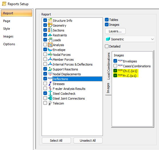
- Displaying values in images of combinations "Characteristic Ch.C.(w1)" and "Frequent Fr.C.(w1)" that do not belong to the mentioned combinations.
- Program 2D FEM crashes when activating the toolbox in reports.
Matrix Tools
- GEO crashes when importing a document with incorrect data.
- Unexpected window enlargement in Cross-calculation MVT.
- Med/(fcdAc) is not calculated in Cross M+N ratio when Ned is equal to 0.
Release notes MatrixFrame® version 6.0-SP2
Processed in version 6.0-SP2 (March 2023)
MatrixFrame® General
- During the insertion of a (sub)structure, loads and load cases were always added. Identical load cases will be merged from now on.
- Dimension lines were no longer placed for a number of loads. This has been improved.
- In a number of cases the P-load decomposition was not performed correctly. This has been fixed.
Reports
- A new selection option has been added to include both the entire model and a selection of the model via the camera option in the report.
- The default print settings for steel connections have been improved.
- A number of places in the Dutch-language reports still contained English texts. This has been resolved.
- Scaling images sometimes resulted in image distortion or large white gaps. This has been improved.
- Dividing mechanics and concrete images to print over multiple lines has been improved.
MatrixTools®
- For masonry calculations, a number of new images have been added for the reports.
Concrete check
- The dialogue for the concrete cover has been extended with a [...] button to determine the strength class.
- Within MatrixBeam, the shear force was not always symmetrical around recesses or recesses. This has been corrected.
- Calculation of the shear force within MatrixBeam has been improved.
Steel connections
- The angle of hook anchors can now be entered from 90 to 150 degrees.
- In a number of cases, identical steel connections were printed twice. This has been fixed.
Swatch check
- In a number of cases, the fire resistance test was not correct for rotated steel profiles. This has been fixed.
MatrixBeam®
- The input grid has been extended with a check of the prestressed reinforcement.
2D Beam Grid/Plate
- During import via an RTF file, the characteristics of the supports are better processed.
Load generator NEN-EN
- In a number of cases, the load due to rainwater accumulation was not determined symmetrically. This has been fixed.
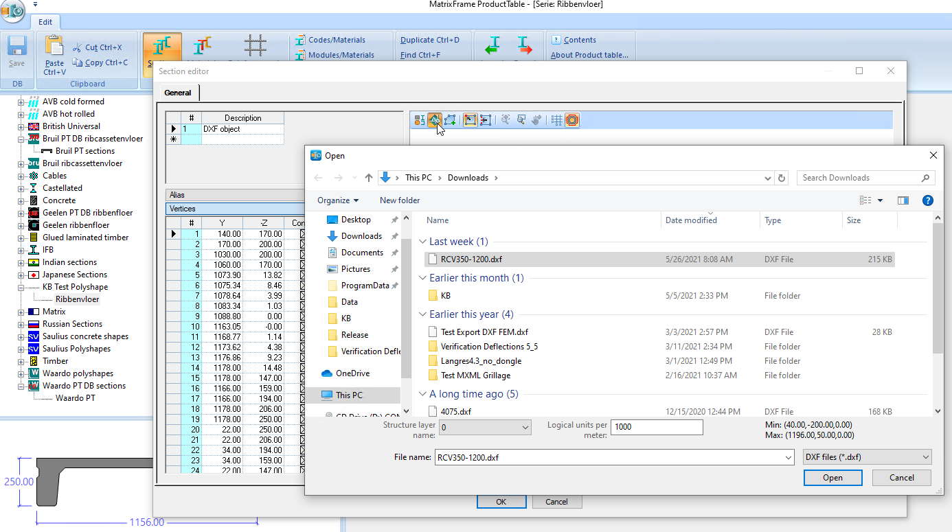
Matrix Product Table (PT)
- The function for importing DXF profile cross-sections within the products table (PT) could not be activated. This has been fixed.
End release note v6.0-SP1
Release notes MatrixFrame® version 6.0 SP1
Processed in version 6.0SP1 (December 2022):
New:
MatrixFrame® General:
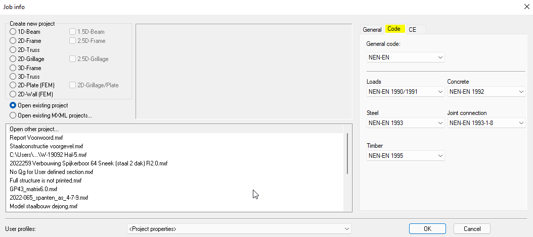
- It is now possible to adjust the Code when starting a new model.
Reports:
- Multiple headers and footers html files have been added so that, for example, the page numbers are at the top instead of in the footer.
- To reduce the empty space between the headers and the first table, "Foreword" has now been added. This in combination with a smaller top margin (1-2 cm.) and with the header "Headersmall.html" ensures tighter reporting.

- Self-created geometry images are now also saved in the user profile (mxp).
- The w1 deflection images have been added to the deflections item.
- It is now possible to use only the file name instead of the file path in the header. For this you must use {?FileName} in the html file instead of {?FilePath}.
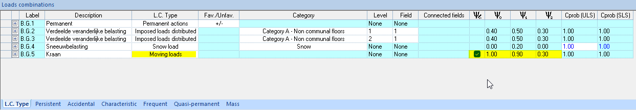
- The table of load combinations has been adjusted to make it more readable.
- It is now possible for the user to select his own style document for Word.
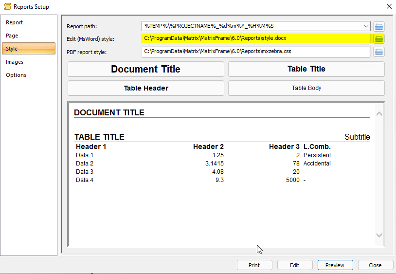
- It is now possible to create your own style.docx to avoid the table headers generated in Word when copying. This style document must be set up once, after which it can be used again and again.
- The headers and footers can now also be activated when "Edit" is selected. Various style.docx documents can be selected for this.
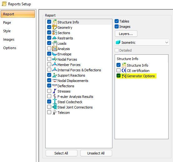
- "Generator options" has been added to item Structure Info.
Link Revit-MatrixFrame®:
- MatrixFrame now has a link with Revit 2023. Revit models can now be loaded into MatrixFrame so that communication between the modeler and constructor runs better. The analytical lines in Revit are converted to an MXML file and the information can be transferred to MatrixFrame. In MatrixFrame, the constructor can perform his/her calculations and send the new sections and materials back to the Revit model.
MatrixBeam®:
- If all patterns have been rejected for a hollow core slab, this is shown in the results xml under "Strip" as "Warning".
Concrete check:
- With the reinforcement for concrete columns, it is now also possible to select several and then with the right mouse button to get an input dialog for filling in reinforcement in 1 go.
Steel check:
- When changing the steel material, the structual members will simply remain intact.
Steel Joint connections:
- When applying a stability connection, it was colored red if no haunch was present. This is now reported in the tooltip.
2D Grillage:
- Distributed area loads are now also copied.
- The offset of the first dimension line, for example of supports, has been adjusted so that the text is no longer placed by the support.
- The button "Internal objects adding mode" is now activated by default for supports and releases.
3D Frame:
- If a distributed area loads is defined in the global Z direction on a vertical member, a message will appear in the log file: Defined loads have no influence on the structure: LD159.
- For an Distributed area load, a small color nuance has been applied to see the difference between, for example, Z and Z'.
MatrixTools®:
- For some modules, where the load generator can be used, the used items are shown in the detailed output.
- The foundation slab module has an extra check built in for the punching check to see whether the punching periphery is within the plate.
Bug fixes:
MatrixFrame® General:
- IFC import dialog was not displayed correctly.
- Incidentally, the user-customized "Quick Access Toolbar" items were reset to default.
- The part description that was entered when creating a new model was not correctly transferred to the model. Here it had to be filled in again.
- With user defined section, the dead load Qg was not calculated.
- It was not possible to deactivate an activated "Non-constructive element group".
- The global coordinate system was not shown in the image of the node displacements.
- The help file of the Macro editor could not be found.
- Incidentally, a concentgrated load on a beam in "Z" was not drawn on the beam. The calculation was correct.
- A distributed load that had a negative and a positive value was not displayed correctly. The calculation was correct.
- If the description of a load was "1.5 m*4 kN/m²", it was changed to "1.5 m*4 kN/mò" after saving and reopening the file.
- Zoom percentages did not work correctly, so the model was out of view.
Reports:
- If there is a "." in the filename, the pdf was not saved in the project folder.
- If there was a "-" in the file name, the report could not be generated and an error message was displayed.
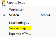
- Saving report settings was not possible because an "Open" dialog was displayed. Now the report settings can be saved and loaded in other applications.
- With MatrixTools, the output language was always set to English on restart.
- During the steel check, some table titles were printed twice in Word.
- Splitting an image into columns and rows did not work correctly.
- Incidentally, in the image only the selection was shown while the "Complete construction" was checked.
- In the enveloping table, the Vz+ was not printed.
- With FEM plate there was too much empty space between the legend and the isometric images.
- The CE certification has been added to item structure info.
- The enveloppe results table did not print correctly.
- The table for the extreme support reactions did not print correctly in the preview or in Word.
- The table for characteristic and frequent support reactions was incorrect and incomplete. The "w1" combination was not printed and where "w1" was written, it was the K.C.1 combination.
- An image of the virtual model was only shown with the first preview.
- An image of the virtual model was shown as a normal construction after saving and reopening.
Loads generator NEN-EN:
- Incidentally, no wind load was generated on an intermediate bar of a duopitch roof.
- Some incomplete translations have been corrected for building type.
Steel check:
- MatrixFrame crashed incidentally after combining structual members, and then immediately executing the steel check.
- Incidentally, combined structual member parts were shown separately in the steel check tables.
- Incidentally, the get bigger section and smaller section option did not work as expected. Values didn't seem to change after multiple clicks.
- When assigning manual/h values for the deflection, these were not entered correctly in the table.
MatrixTools® :
- In the short report for timber beam , the timber quality was not printed.
- In the timber column calculation module, the program crashed if there was a Lsys. entered which was smaller than the L;lateral buckling.
- When opening a file from an earlier version, the language for the reports was set to English.
End release note v6.0-SP1
Release notes MatrixFrame® version 6.0
Processed in version 6.0 (November 2022)
New:
MatrixFrame® General:
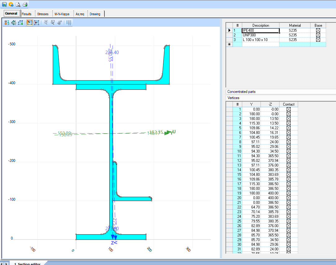
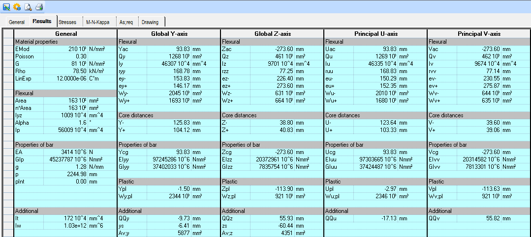
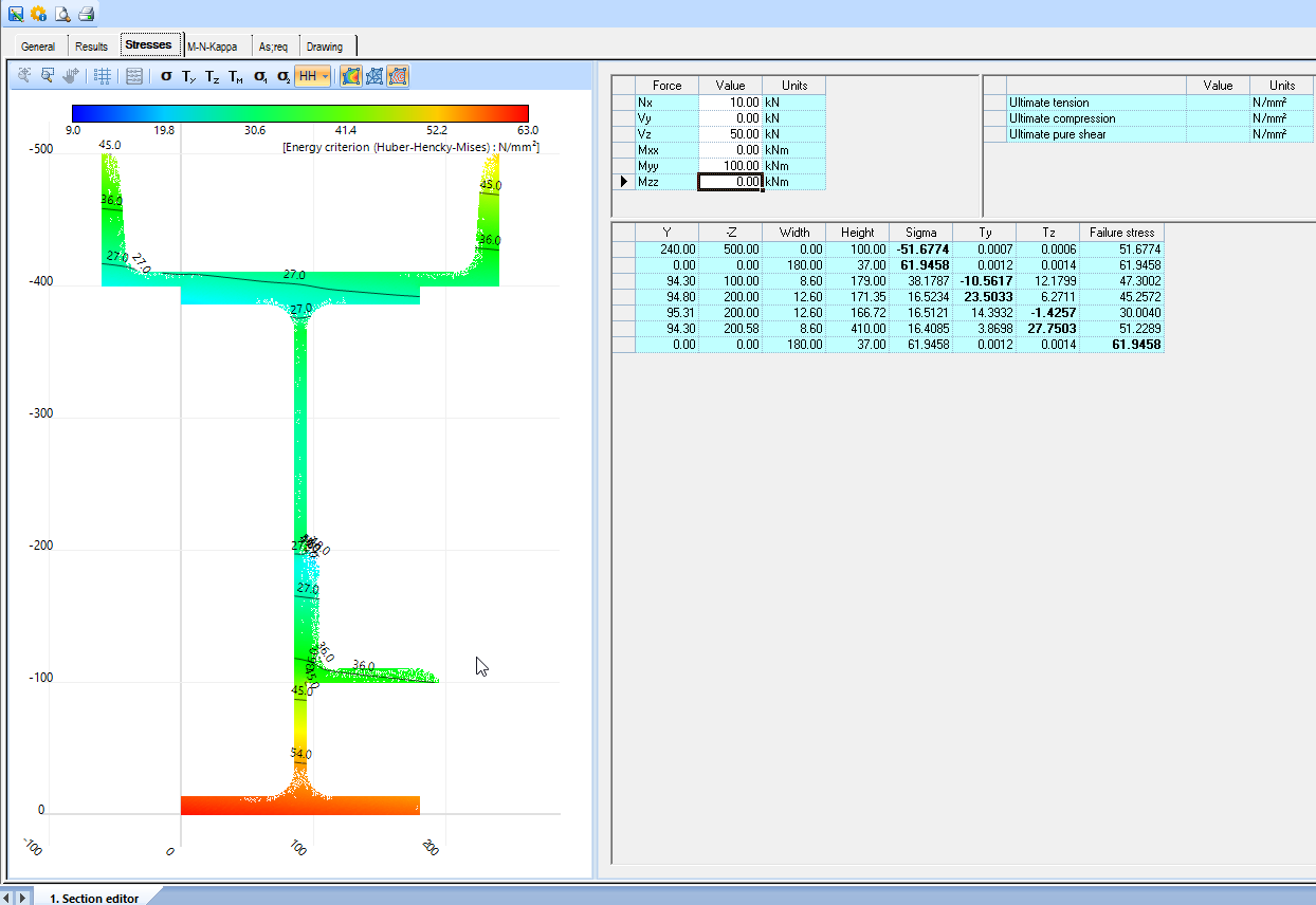
- A new section editor is available for calculating section properties and stresses. M-N-Kappa calculations can also be made and the required reinforcement can be calculated. Section Editor is an extension module
- This new section editor is no longer a separate application, but is housed in the MatrixTools application.
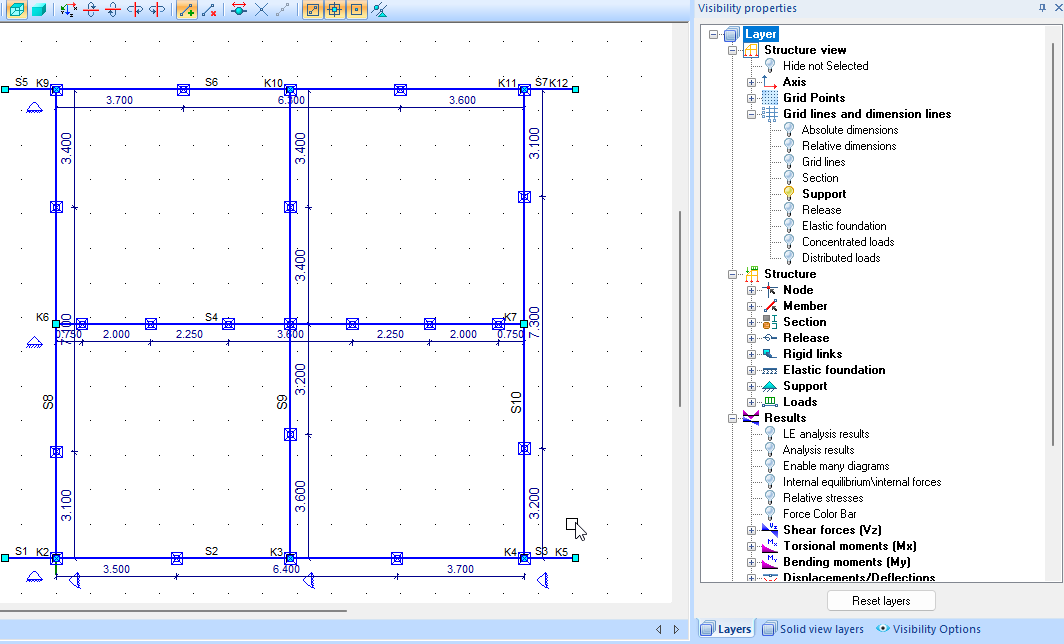
- The visiblity properties have been extended with dimensions for profiles, supports etc.
- It is now possible to change the psi values for mobile loads generated according to the standard. For example, changing the mobile load factors of a crane track.
- Revit 2023 is supported.
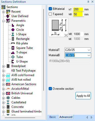
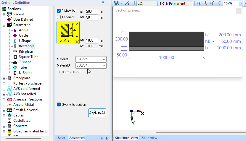
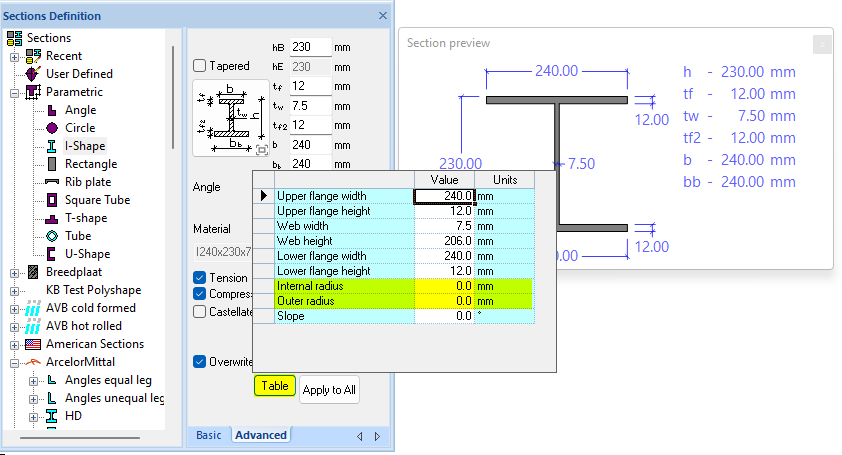
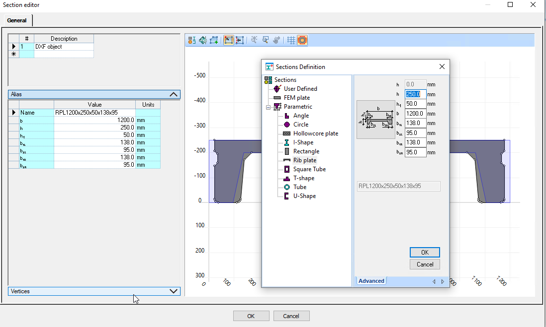
- The section definition dialog for parameterized profiles has been modified and expanded.
- The section dimensions are now specified in mm.
- The image is created dynamically. By clicking on it, it will appear with detailed information.
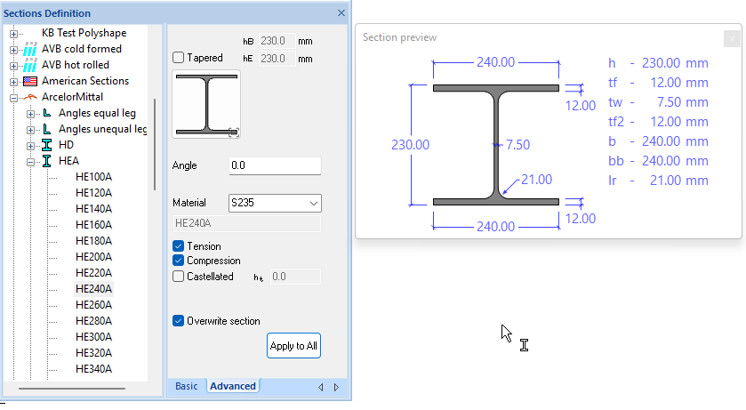
- With the parametric sections, under the tab special, it is now possible to enter the rounding radii for the sections via table. If these are filled in, the profile will be considered rolled. If the value for the rounding radii is set to 0, it will continue to be considered a welded section.
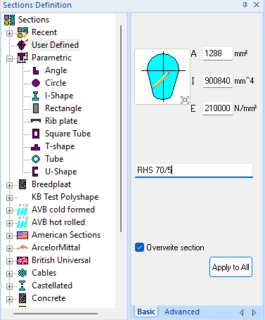
- User defined input is now also in mm.
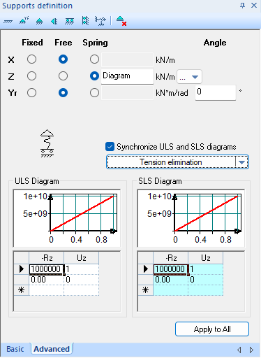
- It is now possible to check "Tension elimination" at the supports in the advanced tab, whereby a correct diagram is automatically generated.
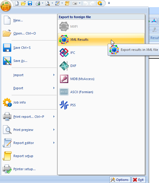
- It is now possible to export a results.xml file, which can then be used to read data and process it in, for example, a drawing. (This is an export xml extension module)
- When importing an "RTF" file, the grid lines are now automatically generated.
- It is now possible to remove loads when a selection with filter is shown.
- If the "Edit loads behaviour" button is activated with an evenly distributed load, the layer is turned on automatically at the same time.
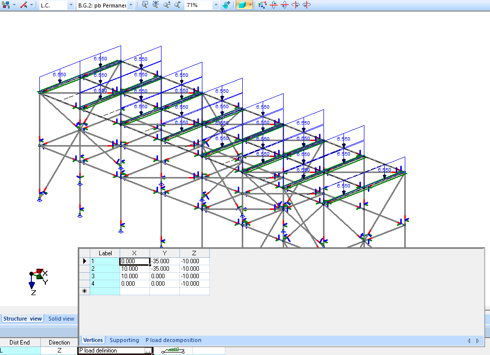
- In the P-load decomposition display, only the distributed loads are now displayed, without the full P-load.
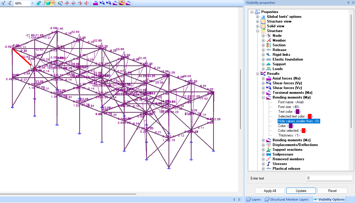
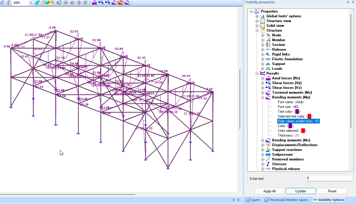
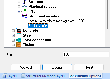
- It is now possible in the "visiblity properties" under the "visiblity options", in all result options with "Hide values smaller than: (0)", make the image more readable by hiding irrelevant small values.
- Example: filter on values less than 0.
- Example: filter on values less than 5.
- Scaling the results has been completely renewed and has now become a global setting.
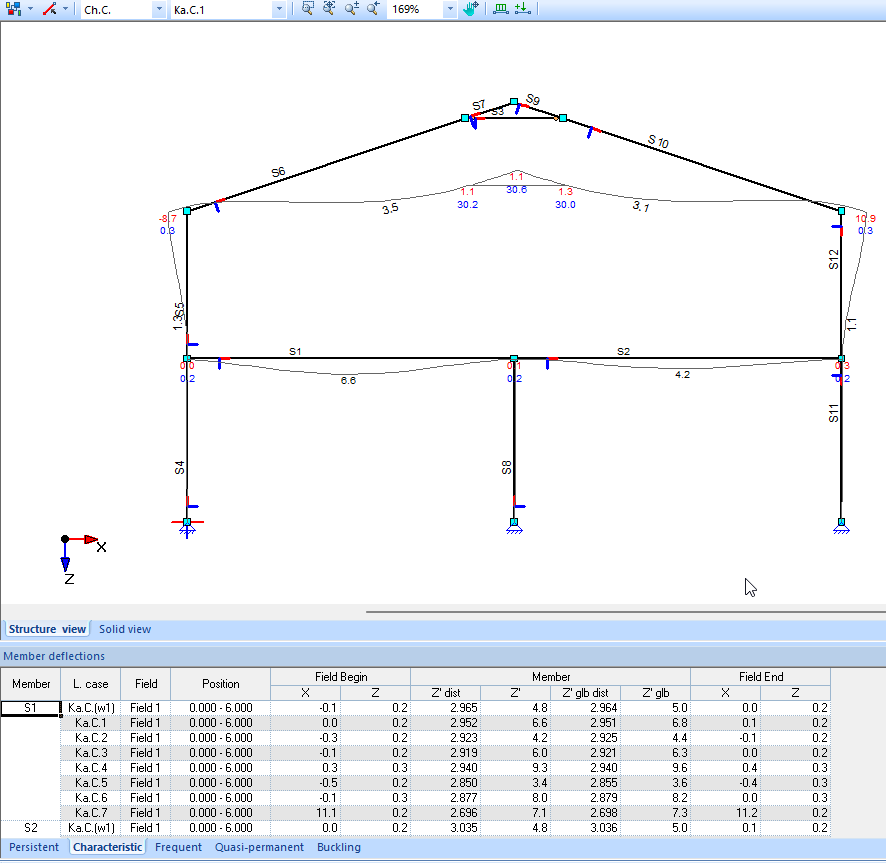
- The node displacements and deflections are now displayed in "mm", both in graphical and numerical representation.
Reports:
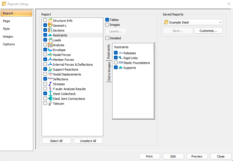
- The reports have been completely renewed. The reports are based on HTML and are presented as PDF.
- In this video an explanation is given about the innovations and the operation of the new reporting system.
- With the new report, the user can create additional geometry images himself. After giving a name, the layers can be adjusted with the ... button.
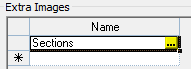
- This image can then be found and used for each report item in the "Camera" tab.
- When printing a "Column+fire" document from MatrixFrame, only the decisive combination is now printed.
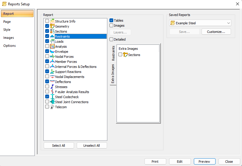
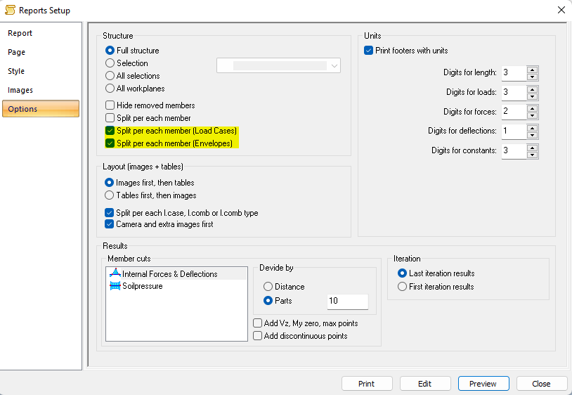
- In the options "Split per each member" has been extended with the possibility to do this only for the load cases and the envelope.
- For the non-detailed reports for concrete, only the crack width data of the set check is now printed. The selected standard article, for example NEN-EN#7.3.3 or NEN-EN#7.3.4, is also included in the output.
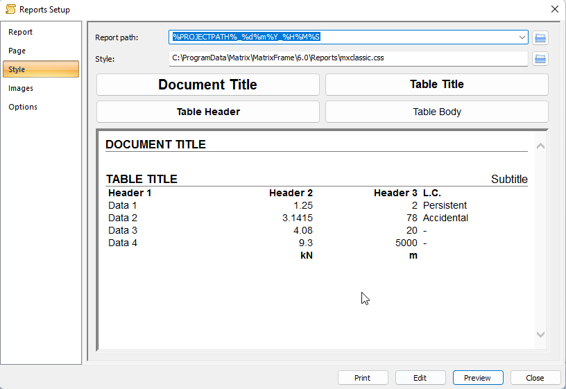
- It is now possible to set a path for the generated PDF in the Style settings..
- It is now possible to save and load the global report settings. This means that you can save the settings in MatrixFrame, for example, and then load them into MatrixTools or MatrixLigger.
- Headers without borders can be set in the *.css file.
- Print tables in print width can be set in the *.css file.
- It is now possible to turn off the bookmarks.
- When choosing to save report, a drop down list of already existing reports is now shown, so that you can choose an existing report to overwrite.
- The number of decimal places for loads used to be equal to the forces but can now be set separately.
- The UCs per load combination have been extracted from the detailed output and added as an extra item.
- When printing with page number greater than 1, the first header was not printed because the program would have already printed it on the first page.
Now it works again as before and if you want to print a continuous report where the full header only has to be printed on the first page, you can choose file " header1stOther.html". - It is now possible to control separately during the concrete check whether the images should be printed during the cross-check or during bar placement.
- It is now possible to switch on the support reactions for the images of the load cases.
Loads generator NEN-EN:
- The national annex "NEN-EN 1991-1-1+C1+C11_2019_NB_2019 nl" has been implemented.
Matrix PT
The Matrix Products table has been extended with the following functions:
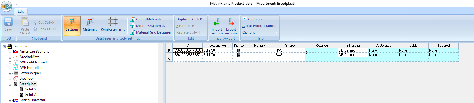
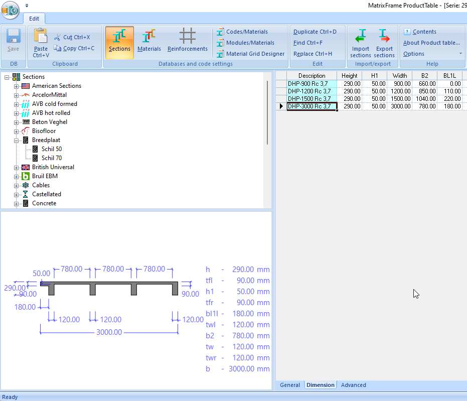
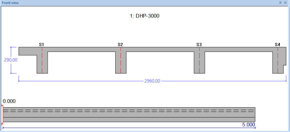
- Users can now define more advanced sections themselves, such as wide slabs with BiMaterial, ribbed floors and hollow-core slabs..
- Another option is to define an random "Polyshape" It can be entered manually or by reading a DXF file. Choose the correct layer name and conversion factor while reading in.
- In order to be able to perform standard calculations for concrete and reinforcement, it is sometimes necessary to define a representative standard cross-section. This can be done via the "Alias" option. This alias can then be chosen parametrically so that the concrete checks can also be performed on the polyshape. This alias is not necessary for hollow-core slabs and rib floors defined as polyshape.
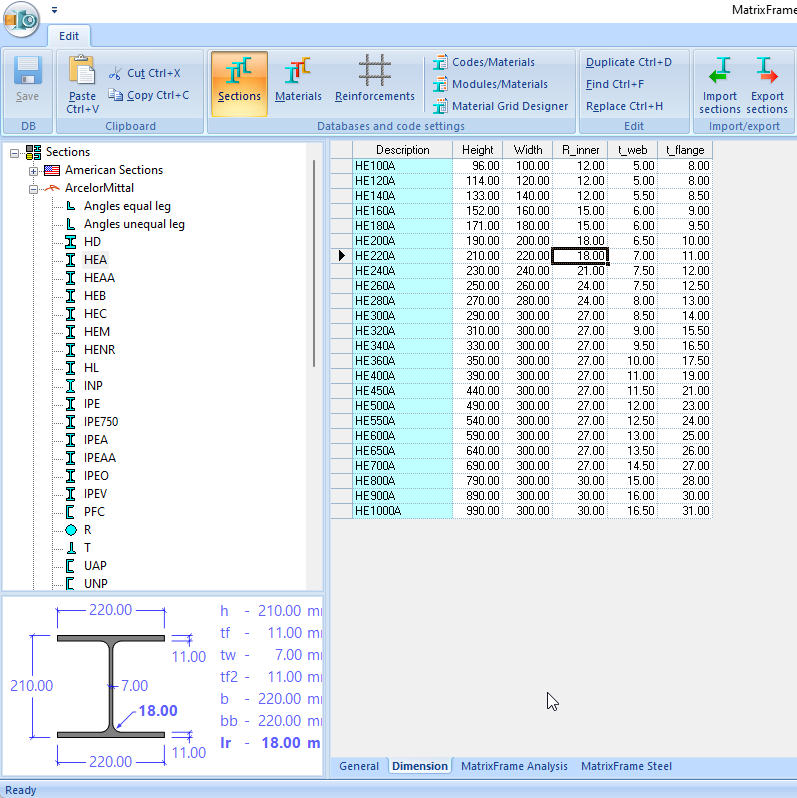
- At the existing sections like for example Arcelor has now added extra information such as rotation, bimaterial, castellated beam and sloped.
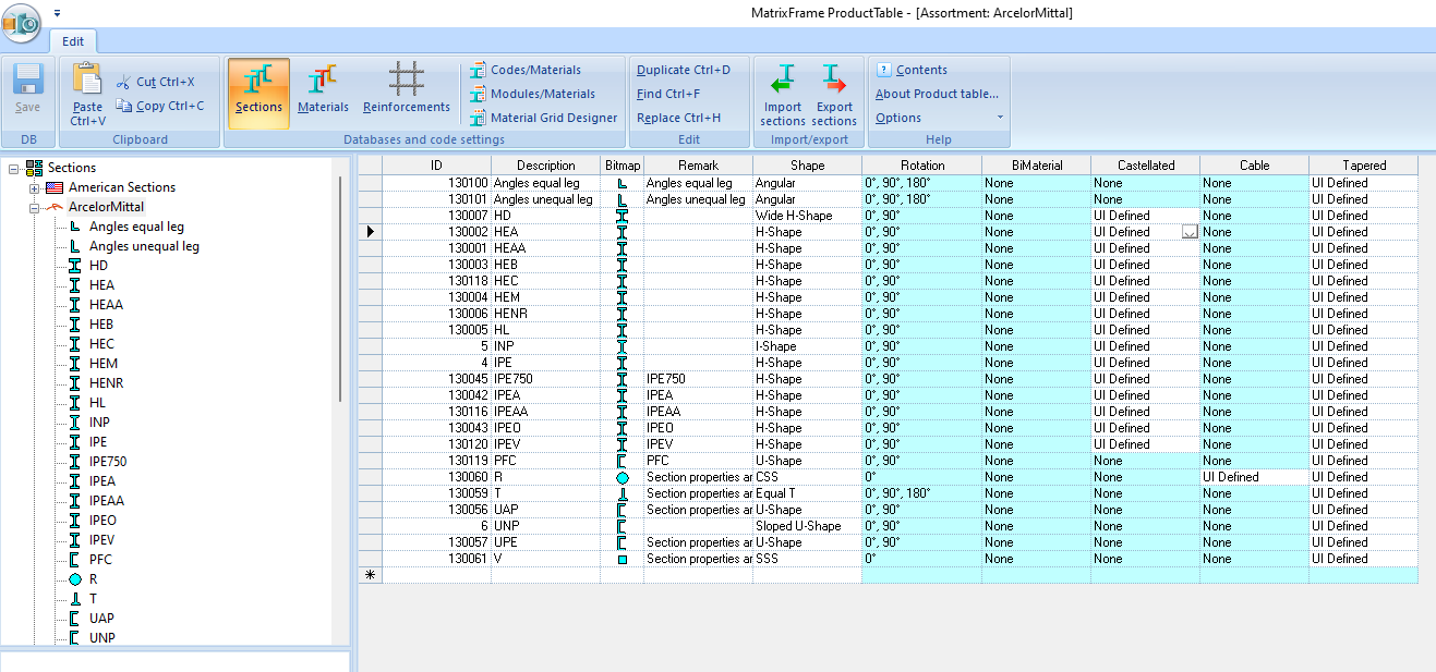
- Images are now dynamic. By clicking on it, detailed information appears and the active cell in the grid is shown in bold.
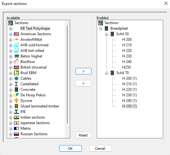
- It is now possible to export and import sectiondata.
- A new type of "ribbed floor" has been added to the Matrix PT with multiple ribs and shapes.
- The Waardo hollow core slabs and prestressing patterns have been added to the product table.
- Reinforcement nets have been added to the product table, as well as Merksteijn nets.
- It is now possible to add a bitmap to self-defined products.
- The timber qualities have been updated.
MatrixBeam®:
- It is now possible to add floor sections, such as ribbed floors, hollow-core slab floors, etc., to the Matrix PT. If desired, parts of the section table can only be made available to a controlled group of users via the Matrix licensing system. For more information, please contact Matrix.
- Added new type of rib floor in the Matrix PT with multiple ribs and shapes. For example, a floor with 4 ribs.
- For the calculation, article "NEN-EN1992-1-1#5.3.2.1 Cooperating flange width (all limit states)" is applied and the element will be divided into individual ribs with the corresponding loads and the results per rib are shown.
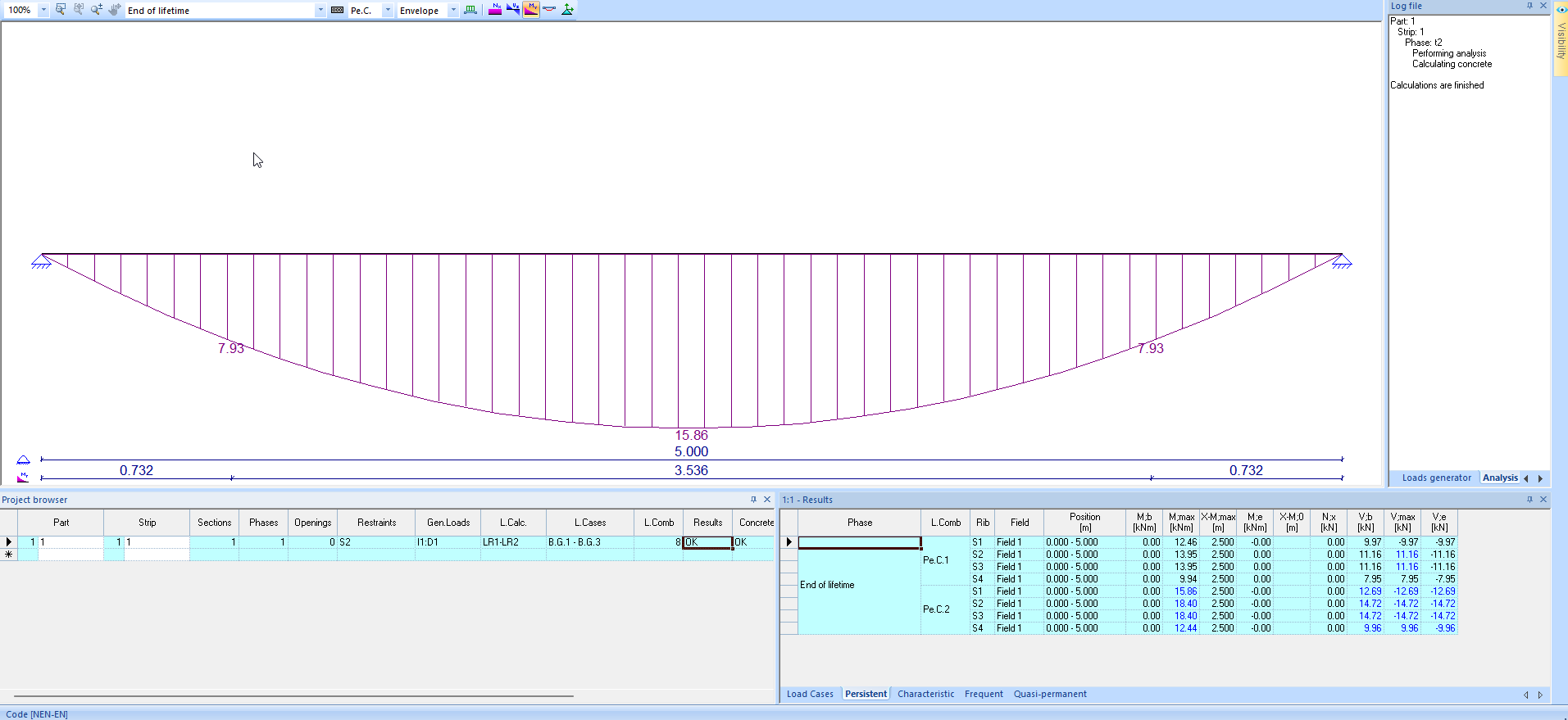
- During the concrete calculation, the ribs are individually reinforced.
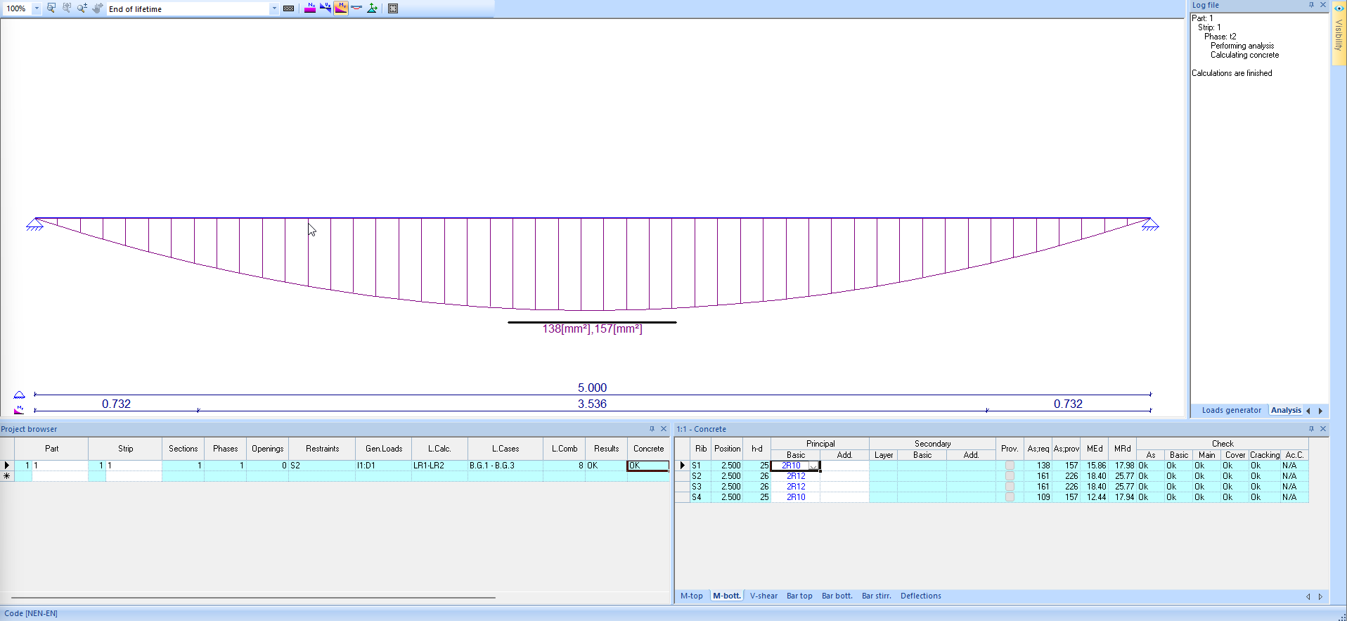
- Area loads and line loads can be applied to the element that are perpendicular to the span as well as parallel to the span. The load will then be distributed over the ribs.
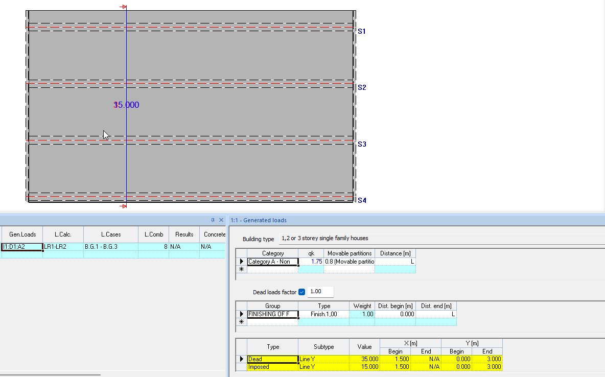
- Load types permanent and imposed are possible and these will be assigned to the corresponding load case.
- Load case permanent load:
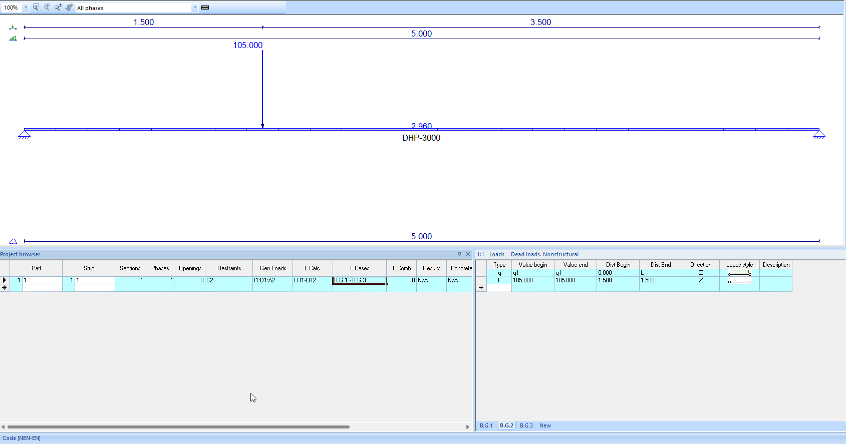
- Load case imposed load:
- The M-NKappa calculations are extensive. It is now possible to calculate with the "Sigma;s+sr" or with "M;s+sr", also the Beta factor can be set to static or dynamic. Additional division points can also be specified.
- If there is a point load, close to the support, in the anchorage area of the prestressing reinforcement, an extra cut is created in the concrete check.
- The value to be generated is now also shown for the movable partitions.
- The persistent and characteristic support reactions, broken down into permanent and imposed, are now also shown with the results on the screen.
- In the Matrix PT (product table), the load widths are in mm. and the self weight in kN/m2 added so that the joint filling and insulation are automatically included.
- A setting has been added to the concrete options to calculate the anchorage length with the a4 reduction factor for welded transverse bars at floors.
- The a1 reduction factor is now also used by default.
- With a multiple rib floor it is now possible to place both a line load and a area load on the floor in X and Y.
- Deflection design has been refined so that it calculates faster.
- If the concrete check gives "Not OK", the tooltip now shows in which check the problem is.
- Added extra settings to combine cuts from different phases that are close to each other for the reinforcement.
- It is now also possible to adjust the dimensions for a selected number of strips via "Set data", for a parametric rectangle with or without an extra layer.
- In the weight widget, the number of joints and strips has been moved upwards.
- It is now possible to enter the number of seams and strips with decimals in the weight widget.
- With the report items it is now possible to check the options of each part on a new page and have each strip start on a new page.
- It is now possible to print the image with all loads with the table of the load cases. This can be done by checking all load cases and load cases with only tables.
- If a change is made in the section cross-section, the selected reinforcement will not be reset if it is still usable for the changed section.
- It is now also possible to have a cross section printed for the phases in the report.
- When calculating the reinforcement for the trimming floor plate of a wide slab, the prefab shell is not included for both the top reinforcement and the bottom reinforcement.
- Reinforcement weight reports are now split into "Rebar weight" and "Additional reinforcement weight". For both options you can choose "Detailed". When detailed, tables are printed for each strip and a total table. Not detailed, only print the total tables.
- It is now also possible to calculate kg/m2 for strips with different thicknesses and widths.
- The reinforcement of a trimming floor plate is included in the connection reinforcement for the weight. This is because the reinforcement lies on the plate and not in it.
- In the case of a rib floor, in which there are no stirrups, the reinforcement proposal will ensure that VEd < VRd;c.
- For stirrups on the slab, a "zi" of 0.9*d is used, whereby for "d" the thickness of the top lauer is used.
- Bar placement stirrups has been added to the concrete widget.
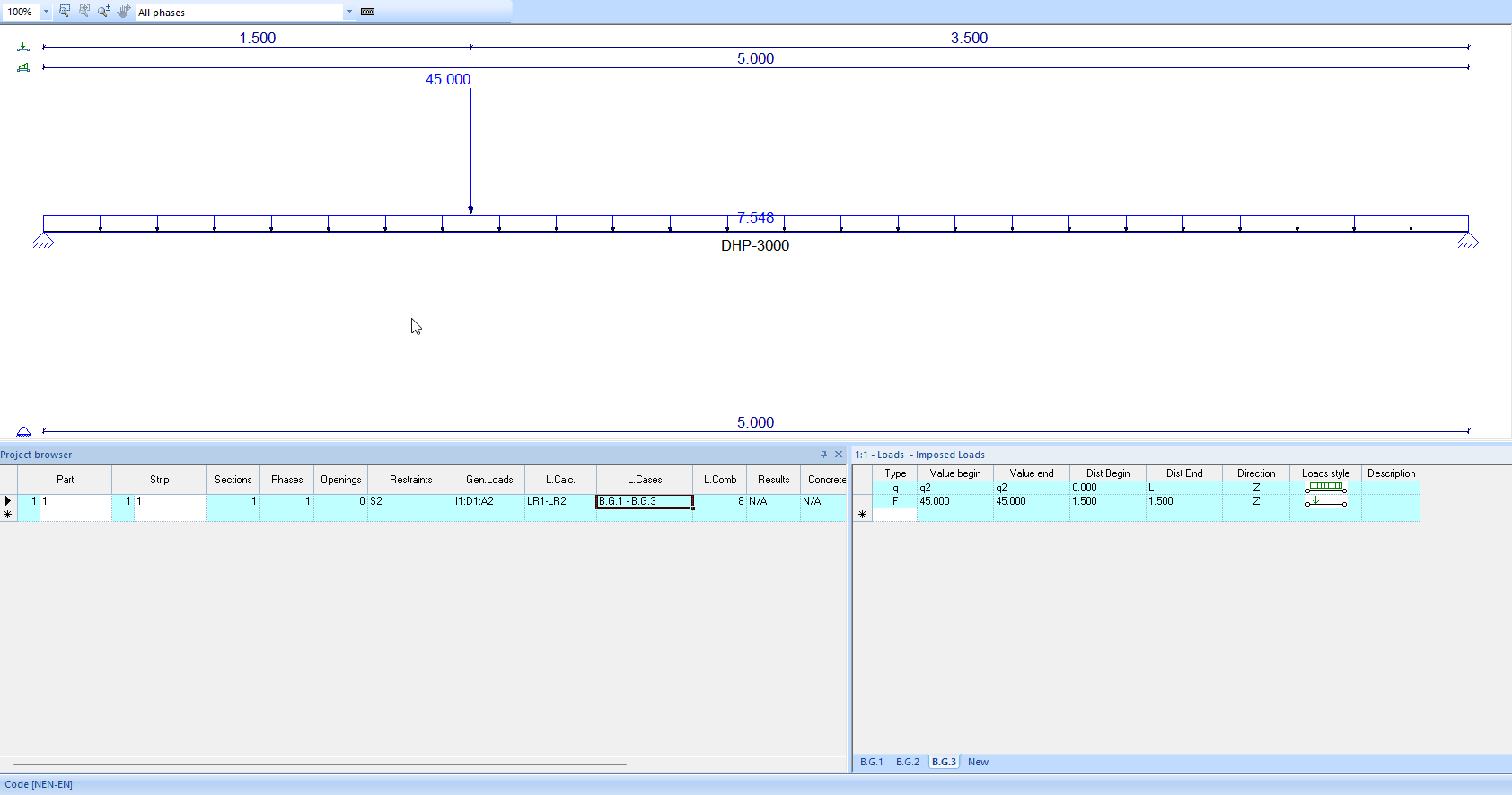
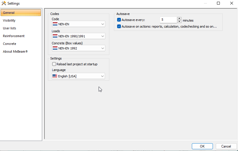
- Autosave has been added so that no more than 5 minutes of work is lost in the event of an unexpected crash of the program.
2D Frame:
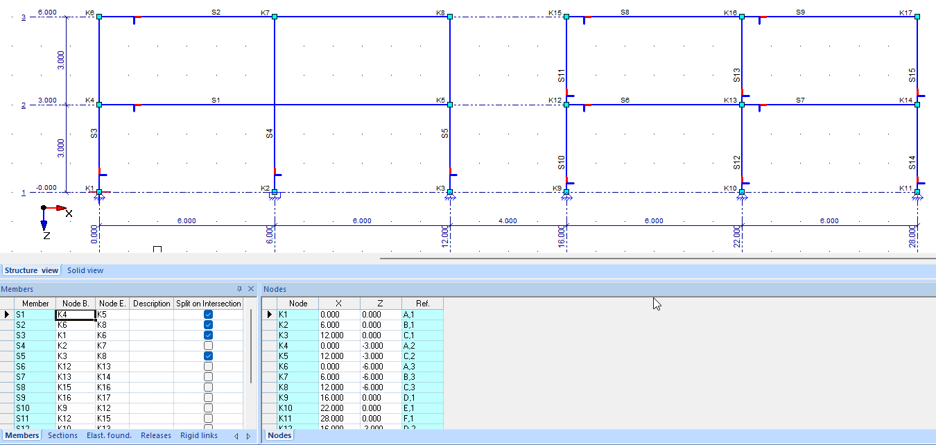
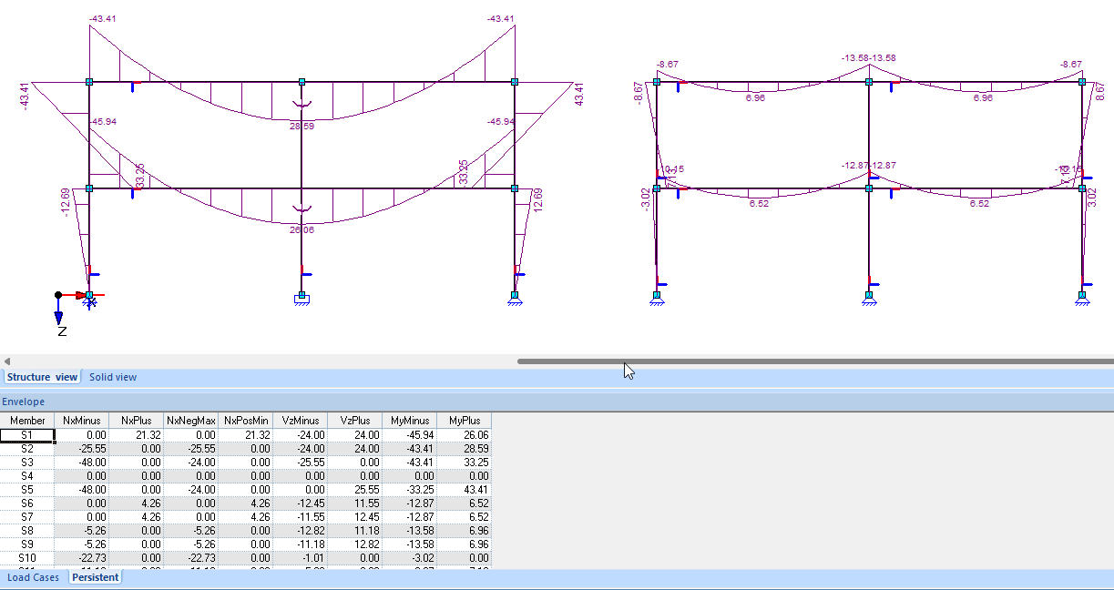
- It is now possible to model with structual member as in 2D Grillage. For this purpose a column has been added in the member table "Split on intersection". By checking this, the member will be seen as linked during the calculation.
- In the picture below, the left part is modeled with structual members and the right part is traditionally modeled with split members at the place of the construction. a connecting or intersecting member.
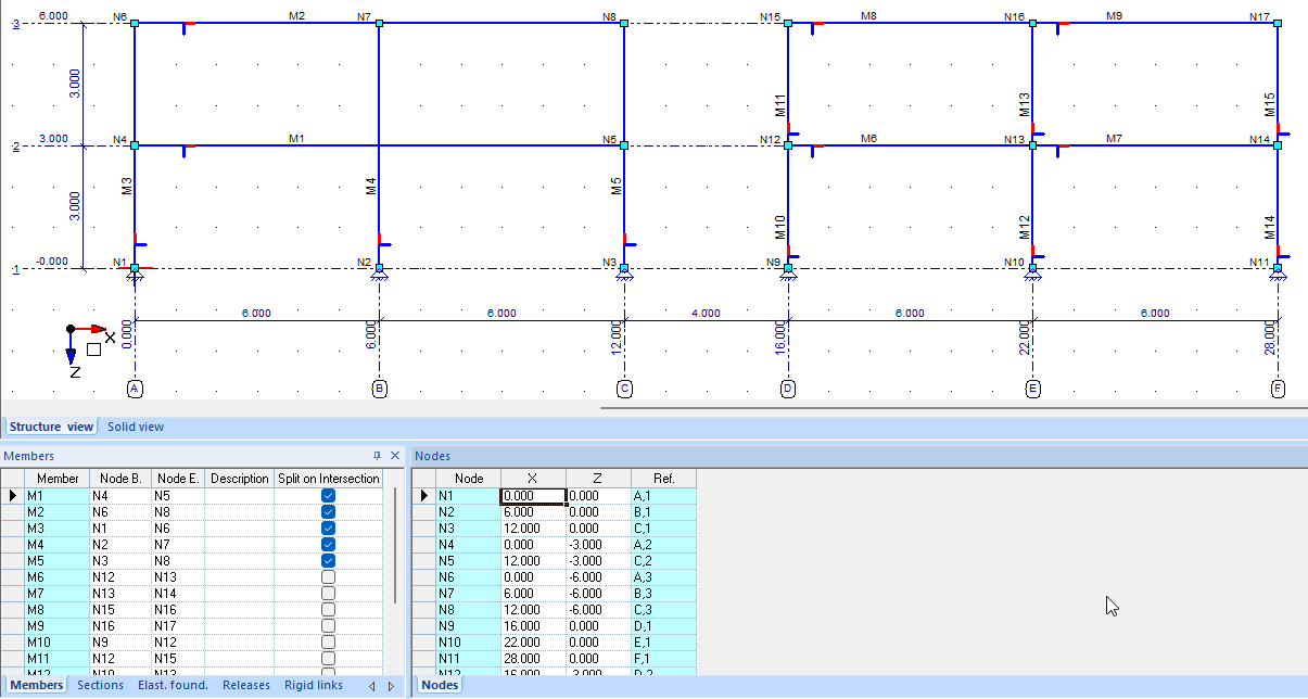
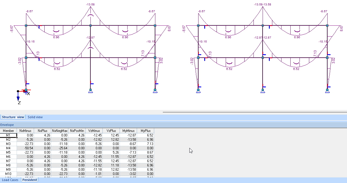
- Below the results if member for is not checked.
2D Grillage:
- Active dimension lines have been added for supports, releases, elastic supports, concentrated loads and evenly distributed loads. The dimensions can be adjusted by clicking on vertical position dash line.
3D Frame:
- It is now possible to model with structual member as in 2D Grillage. For this purpose a column has been added in the member table "Split on intersection". By checking this, the member will be seen as linked during the calculation. For images, see 2D Frame above.
- If the model gave a lot of "Geometrically unstable system" messages, the "OK" button was no longer visible. Now only the first 10 and last 10 notifications are shown.
FEM:
- It is now possible, with the multiple core processor, to check "Tension elimination" at the supports in the advanced tab, whereby a correct diagram is then automatically generated.
- It is now possible to graphically choose the points for the lines in the spy function.
- It is now possible to place a trapezoidal load on a plate.
- If you have selected everything, such as point, line and area, right mouse menu now gives you the move point dialog.
- It is now possible to export a dxf containing the geometry, supports and position of the loads. Loads are put in 1 load case with value 1,000 kN.
Concrete check:
- If accidental combinations are defined, which are not for fire, they will be checked correctly by checking the fire check with a time of 0 minutes.
- For accidental combinations manually created by the user, the fire tab and the checkbox are now automatically activated. This also checks for the required reinforcement in the last column "Acc.C."
- Reinforcement diameter R14 has been added to the default reinforcement table.
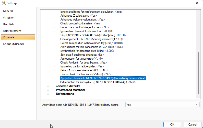
- Nowhere in the standard is the check for the maximum bar distance for flank bars for ordinary beams, only for deep beams something is mentioned. In the GTB, the control is shown here in an image.
In order to be able to perform this check, a setting has now been added to the concrete options "Apply deep beam rule NEN-EN1992-1-1#9.7(2) for ordinary beams" where the setting is set to "Yes" by default.
Steel check:
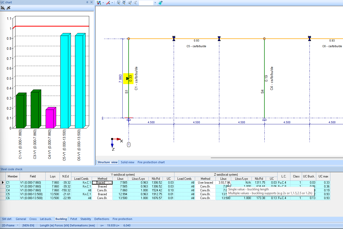
- A structural member check has now been entered so that in case of changes only the data of a changed structural part has to be reset. All other data already entered about lateral buckling, buckling etc... remain intact.
- It is now possible to specify the position of the buckling supports. A buckling support has been placed in the Y-axis for C1. Now both the lower part and the upper part are checked for buckling.
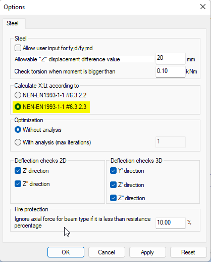
- Added possibility to do the check for lateral buckling according to NEN-EN 1993-1-1#6.3.2.3.
- If the unity check is already greater than 1 for the single checks, a * is now shown in the sample report with the text "* - Individual checks failed, combined checks were not performed."
- It was not possible to specify unbraced in 2D with the buckling method in the Z-axis. As a result, the Cmz was never set to 0.9. Now you can choose "Manually unbraced" or "Manually braced".
- It is now also possible to split 1 combined structual member to seperate members again.
- It is now possible to reset the sample check. This can be useful if an existing model has been modified a lot.
- In the 3D Frame, the notification about torsion check has been adjusted to: Torsion check is done according to NEN-EN1993-1-1#6.2.1(5) if moment > 0.1 kNm.
Timber check:
- The timber check has been completely redesigned to use equivalent sections.
- It is now possible to combine different sections into 1 structual member with the timber check, just like with the steel check. The stability is then calculated with an equivalent section, which is set by default to the weakest cross-section.
Steel Joint connections:
- Added juncture calculation at "Column base plate".
- The M-Phi diagram is now also generated for a base plate calculation.
- It is now possible to use a single row of anchors for a column base plate connection with a RHS or CHS section.
- For truss connections, the dialog to specify the distance between the wall beams has been modified. Now you can choose between the distance of the beams or the centerlines. If you choose centerlines and set this value to 0, the centerlines will all coincide.
- With truss connections, the center lines of the wall bars are now extended.
MatrixTools®:
- New section editor which only works on a 64 bit Windows version for calculating the stresses. On 32 bits he can determine all other properties.
- In the new section editor, the option to move has been added under the right mouse menu.
- Added a new module to "Junture calculations" to the "CT Concrete".
- Addition calculation also added to "Column calculation + Fire".
- The new juncture control module has been added to the concrete columns and base plate calculation at the steel connections. This can be activated or deactivated via the settings.
- With the timber beam modules it is now possible to set the load combinations for, for example, the NEN 8700.
- Concrete column and Fire + MVT + M-N-Kappa and Juncture calculation can now be used with the API with JSON.
- In the masonry module "Concentrated load" the entry of the "Wall length L" has been added. This is to do an extra check for the calculated "Lef." This is because in NEN-EN1996-1-1, #6.1.3(2) formula 6.11 a reduction must be applied based on Aef.
- An extra "Max. height (drawing)" has been added for the images to the new reports.
- For the punch module, the check according to NEN-EN1992-1-1#6.4.4 (2) Perimeter between 0d and 2d has been added.
- In the output of the welding calculations it is now also visible whether the framework is statically determined or statically indetermined.
- The reduction of the welding capacity is now also included in the output.
- The calculation according to NEN-EN1992-1-1#6.5.3(3) has been added for the 2 pile foundation block with strut & tie.
MatrixTools® Geo:
- It is now also possible to work with a mirrored coordinate system when digitizing a CPT. Normally the friction is to the left of the 0-line and now it is also possible to click to the right of the 0-line if the warning is clicked yes to continue.
- The friction trajectories entered by the user are now also remembered and saved in the model.
- The friction trajectories can now be entered in the interface of the compression and tension pile. As a result, the user does not have to return to the soil layers in the CPT every time.
- When reading a GEF file, where no cone values have been entered, a message is now given.
- The negative friction factor used has been added to various tables in the reporting items "Compression pile summary per CPT" and "Compression pile detailed".
- The "Screwed tube pile" has been added to the pile systems.
- The item used for the crack width check is now printed at the output of "Bening moment pile".
Bugfixes:
MatrixFrame® General:
- Walls and floors are now always correctly converted to the correct work plane.
- Link from Revit with recognition of sections and materials has been further tightened. The section orientation of the local axes has also been improved. The 90° rotation of the model has also been solved.
- When clicking on the "Save" button, or the key combination "Ctrl+S", the save as dialog appeared regularly instead of the model being saved immediately.
- In an advanced calculation with GNL and FNL, a 90° turned tube was not processed correctly.
- MatrixFrame crashed intermittently when quickly changing load combinations in tables.
- Stresses were occasionally not shown graphically.
- When importing an "rtf" file, the load combinations printed on a 2nd line were not read.
- Occasional snap to grid line didn't work if the layer wasn't on.
Reports:
- Occasionally MatrixFrame crashed when generating a report of a steel connection.
- When printing "Load cases per beam (incl. Image)" the table was incorrectly printed first and then the image. This has now been reversed.
- When opening a file from Google Drive, the program was occasionally closed when creating a report. This issue has been resolved with the new report system.
- With a large 2D Grillage, when printing the images, not all beams were scaled correctly per beam of a selection of the envelope.
- If the user had set a cover.html and/or his own *.css file, these were restored to default files after closing MatrixFrame and restarting.
- For a FEM plate, all images of the stresses were printed during the report, even though they were not selected.
- Logo was not scaled correctly. Also, 2 new headerlogo html files have been added.
- Images were rotated in the wrong direction when rotated.
- The "Extra Images" dialog occasionally disappeared when you pressed "esc".
- When printing a selection, the loads calculation sheet is now also printed.
- Structual engineer was not printed in the Header.
- For 2D Grillage, the orthogonal top view images were drawn if split per each member was enabled.
Loads generator NEN-EN:
- With the rainwater accumulation, the changes of the default generated position of the drain were not saved.
Matrix PT
- When opening the product table, the values of self-defined materials were set to 0. This was only a problem when opening the previously entered values were used correctly in MatrixFrame and other programs. Before saving again, the workaround was to re-enter the values.
MatrixBeam®:
- With a floor with reinforcement type "Strip", stirrups are now only applied over the area where they are needed.
- The calculation of the kg/m2 for the lower reinforcement has been adjusted. A slightly too high value was calculated.
- With a rib floor, if a T or L profile was used, a stirrup was incorrectly charged for the s;min check.
- For prestressing with recesses at the top, a corrected "dp" is now calculated.
- For a pre-tensioned strip, the fire control has been adjusted. Now a new load case is generated with the reduced preload due to the fire.
- The values of this can also be found in the loads calculation sheet.
- Note: When opening an old model, both the loads and the combinations have to be regenerated.
- When changing the number of supports, the loads and combinations were no longer automatically regenerated.
- Incidentally, the bar placement from stirrups for a strip, the stirrups were incorrectly installed over the entire field length.
- When clicking quickly between results, concrete and load cases, the program closed without warning.
- It was not possible to enter a time of 0.33 days for a hollow-core slab for phases.
2D Grillage:
- During the steel check, the specified camber was not always processed for an cantilever.
- With the dxf in 6.0 Beta the piles were no longer drawn and it was no longer possible to use new pile types.
3D Frame:
- Incidentally, MatrixFrame crashed when opening a model, which also included steel connections, which was saved with results.
- Incidentally, an IFC file exported from MatrixFrame became corrupt because it contained "IFCDIRECTION((-NAN(IND),-NAN(IND),-NAN(IND)))" in the file.
- Incidentally, an distributed are load in local Y' was not validated correctly. As a result, it was colored red and MatrixFrame crashed when starting calculation.
FEM:
- If you had selected everything, such as point, line and area, right mouse menu would not give you the move point dialog.
- Incidentally, a stair recess, on the edge of the plate, was not correctly recognized and the mesh did not see it. Generating the grids again usually solves this.
- With FEM plates and walls, qg was only used once in the calculation and always with a factor of 1. Now several qg loads can be assigned.
Concrete check:
- In a 3D construction, only 1 structual member was detected in the concrete calculation.
- When bending and axial force were calculated, including the setting for an extra cut when changing axial force, this extra cut was not always generated.
- In the 6.0 Beta, the bar placement for stirrups were occasionally not completed correctly.
- Incidentally, MatrixFrame crashed when a concrete column was placed on all-sided reinforcement in 3D.
Steel check:
- During the bending & compression check, for an unbraced construction around the Y-axis, the Cmy was incorrectly not always set to 0.9.
- It was not possible to specify unbraced in 2D with the buckling method in the Z-axis. As a result, the Cmz was never set to 0.9. Now you can choose "Manually unbraced" or "Manually braced".
- During the steel check, the specified member was not always processed for an cantilever.
- During the steel check of strip on cantilever, an unfavorable table was occasionally used for the lateral buckling, depending on the sign of the moment.
- In 6.0 Beta, after modifying an existing structure, the structual members were not always reset correctly.
- Incidentally, for a symmetrical model with tapered profiles, the UC was not symmetrical.
- In 6.0 Beta tension only beams were not always recognized as structual member and therefore not checked.
- The buckling lengths for unbraced and braced were not calculated correctly, and set to system length, if buckling combination 1 was not checked.
- The torsional moment was not shown in the table during the cross-sectional check. This was mentioned in the export.
Houtcontrole:
- During the deflection check of a composite structural part, the global deflections were tested instead of the local ones.
Steel Joint connections:
- For a portal, where the beam lies on the 2 columns, when these were calculated as a group, the forces for the right node were converted incorrectly.
- During the welding check, an incorrect reference was made in the report to "NEN-EN 1993-1-1 #4.9" this had to be "NEN-EN 1993-1-8 #4.9".
- For truss connections, the dialog to specify the distance between the wall bars has been modified. Now you can choose between the distance of the bars or the centerlines. If you choose centerlines and set this value to 0, the centerlines will all coincide.
- Incorrect check from the "NEN-EN-1993-1-8 table 7.8" "bi/bj <= 0.75" corrected in "bi/bj >= 0.75". Also the control for K and N with spacing bi/b0 >= 0.35 corrected in bi/b0 >= 0.25. These corrections have been verified with multiple editions of steel connections books.
- With truss connections, the center lines of the wall bars are now extended.
- If a RHS column was applied both below and above a beam, it was shown as a HE profile in the drawing.
- If a model with steel connections was added to an existing model, these connections were displayed incorrectly because the beam information was not read correctly.
- In the case of a T-connection with a tension plate, when a pressure partition was placed, in combination with a positive moment in the beam, this was incorrectly checked as a tension plate.
- With a connection of a tapered section, for example IPE330(330-550) where the 550 is on the column side, the correct height was not calculated for the bar cross section check.
MatrixTools®:
- In the preview of the concrete cross-section M+V+T, the flank bars were not always visible. Problem was they were drawn on the stirrup line.
- In the concrete module "Column calculation + fire", the test on the s;max was incorrectly no longer performed.
- With a concrete column it was wrongly possible to specify different reinforcement (For example 2R20+3R16 ) with the basic reinforcement. Calculations were then made with 5R20, but now the reinforcement is colored red in case of incorrect input and you can see why in the tooltip.
- In the punch calculation strange negative values were occasionally shown for VEd.
- Incidentally, at a small increase in the punching force, the punch module came with a gigantic amount of punch reinforcement while no punch reinforcement was required before.
- When opening a Brawesta file, with a parametric section, the section properties were not calculated, so the check was not performed correctly. After redefining the section, the problem was solved.
- In Brawesta, no profile factor was calculated for a solid rectangular cross-section.
- In a rectangular base calculation, the check has been added that the foundation width must be equal to or greater than the foundation length.
- In a square base calculation, the check has been added that the column height must be equal to or greater than the column width.
- When generating Mu2 for snow, on a flat roof, the Sk was incorrectly set to 1.0 instead of 0.7 .
MatrixTools® Geo:
- Incidentally, a GEF file read in was not scaled correctly. For this, the "Automatic grid adjustment" setting has been improved.
- In the module "Bending moment pile" values and checks such as "Not OK" were incorrectly printed in the report at the "Reinforcement results (SLS)" for the cuts where there was no reinforcement.
- The image for a foundation strip was not always correctly scaled when the ground level was above N.A.P.