What is new in version 2026
Please be aware that you are using a beta version of the software. Although extensive testing has been done, users should exercise caution and maintain backups of all projects. Unexpected behaviour may occur, and we encourage users to provide feedback for ongoing improvements.
General
Calculations in accordance with the Second Generation Eurocode [G2] are now available for testing and comparative evaluation.
The implementation currently includes the following normative documents:
- EN 1990:2023 — Basis of structural and geotechnical design
- EN 1991-1-1:2025 — Actions on structures — Part 1-1: Specific weight of materials, self-weight of construction works, and imposed loads for buildings
- EN 1991-1-3:2025 — Actions on structures — Part 1-3: Snow loads
- FprEN 1991-1-4:2025 — Actions on structures — Part 1-4: Wind actions
- EN 1992-1-1:2023 — Design of concrete structures — Part 1-1: General rules and rules for buildings, bridges, and civil engineering structures
- EN 1993-1-1:2022 — Design of steel structures — Part 1-1: General rules and rules for buildings
- EN 1993-1-2:2024 — Design of steel structures — Part 1-2: Structural fire design
- FprEN 1995-1-1:2025 — Design of timber structures — Part 1-1: General rules and rules for buildings
The use of the Second Generation Eurocodes [G2] can be activated by selecting the General code optional setting:

Important note: All Second Generation Eurocode calculations implemented in the software package, including corresponding UI options, tooltips, and informational reports, are explicitly marked with the “[G2]” tag. Any options or reports without this tag refer to the currently used (first-generation) Eurocode normative documents.
MatrixFrame
Additional functionality has been introduced with the Take picture button.
Users now have two options instead of a single Copy button: Copy vector image to clipboard (EMF format) — preserves quality when zoomed and maintains a transparent background; Copy bitmap image to clipboard (BMP format) — creates a standard raster image.

The UI visibility setting for displaying the number digits has been moved.
The UI visibility setting for displaying the number has been moved to Options → Units. The value defined there will now be applied uniformly across all application chapters.

Definition of parametric steel sections. An optional parameter for the definition of weld height is added.
Implemented the functionality to define the weld height (as the weld radius) for parametric cross-sections of the following types: L-Angle, I-Shape, U-Shape, and Square/Rectangular Tube. The optionally specified weld height is now considered in the section classification, but it is not included in the calculation of the section properties.
The weld height can be entered in the Section Definition dialogue. To do this, open the Advanced tab, click the Table button, and manually input the required weld height. Alternatively, the weld height may be specified directly in the Sections grid table under the Shape tab.
Input is allowed only when the inner radius value is set to 0. If the inner radius is not 0, the weld height is reset to 0 and disabled.


Enhanced representation of the support reaction envelope on a FEM plate.
Implemented an enhanced feature that enables the display of the support reaction envelope on a FEM plate for both the top and bottom sides simultaneously within a single drawing. This improvement is particularly beneficial for structures with concentrated supports, providing a clearer and more comprehensive representation of the reaction distribution.

A new system for managing code box values has been implemented.
Customize → Box values for Concrete, Steel, and Timber are now unified into a single dialogue. When saving box values, they are written to a file using a name provided by the user. If a file with the same name already exists, the user is prompted to confirm whether the existing file should be overwritten.
All applications now use a shared settings file. As a result, if box values are modified in MatrixFrame, the same values will automatically be applied in MatrixTools and MatrixFloor at their next launch, and vice versa. The most recently used box values are always saved.
If a project is opened using custom box values and the application is later closed, those same box values will be applied automatically when starting a new project. When custom box values are active, reports in all code-check modules (Concrete, Steel, Timber, and JointCon) include a note indicating that user-defined box values are being used. This behaviour is consistent across all products (MatrixFrame, MatrixTools and MatrixFloor).

Implemented regulatory updates for calculations in accordance with NEN-EN 1992-1-1 + C2 + A1 / NB + A1 + A2 (NL), May 2025, Chapter 6.2.2 — Elements that do not require shear reinforcement calculation.
Changes anticipate the upcoming Eurocode 2 revision, particularly for the shear strength of large concrete sections. Changes recognize that shear resistance for large cross-sections (≥ 0.5) was previously overestimated. New rules in 6.2.1–6.2.2 define verification procedures for elements without shear reinforcement and specify cases where verification may be omitted.
Customization of the image properties for Steel, Timber, and Concrete code-check objects within Reports is implemented.
It is now possible to customize the image properties for Steel, Timber, and Concrete code-check objects within Reports setup independently from the settings defined in the UI Visibility options. This allows report images to be formatted differently without altering the global UI presentation settings.

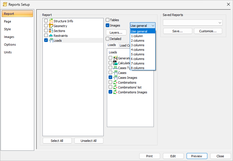
A new reporting feature has been introduced that enables images to be arranged in multiple columns.
The number of columns can be configured individually for each report group, or, by selecting the Use general option, applied universally to all report sections based on the value specified in Reports Setup → Images → Columns.
MatrixTools
The Column Base application has been updated with new functionality. It is now possible to add additional rows of anchor bolts on the tension side of the column base.
A new option has been introduced that allows the rows of anchor bolts to be arranged asymmetrically with respect to the column’s central axis, while still enforcing the requirement that only one row of bolts may be placed on the outside of the column.
To use this feature, enable the "Manual" checkbox in the "Anchors" tab of the Column Base application, then add the new row of anchor bolts in the anchor bolt grid.
