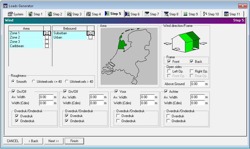
Fig 1. Loads Generator Step 5: Wind
Loads Generator recognizes wind impact on structural elements. You are expected to define parameters for the wind loads calculation.
Available wind geographical zones of the Netherlands are represented in Area grid. Selected zones are shown on Region map. Belonging on the regions terrains are listed in selectable Terrain Category grid and must be selected too.
Surface roughness:
- Smooth surface
- <=40 mm - small roughness
- >40 mm - rough surface
Wind direction in respect of building (from left, from right, from front, from back) with parameters:
| Parameter
|
Description |
|
Average width (qp, b) |
average width value [m] is used for calculation of qp (in the EN and EN-National code mentioned as b, in NEN6702 mentioned as Pw) and CsCd. This parameter indirect describes blown surface |
|
Width (Cdim) |
value describing distance [m] between the structure frames (see System) |
|
Overpressure |
wind pressure from inside (negative internal pressure) |
|
Underpressure |
wind pressure from outside (positive internal pressure) |
Wind frame parameters:
|
Parameter |
Description |
|
Frame |
frame origin [m] by Y axis (front, back); relative frame origin selection is highlighted in figure |
|
Above Ground |
reference height for determining the structural factor [m] |
|
Open sides |
available openings (open spaces through which the wind enters the surface) in structure sides (left, right, front, rear) |