"Structure View" is the graphical representation of the structure and all related data. Dependent on the project part activated "Structure View" enables appropriate specific commands in the graphical area: General, Structure input, Loads input, Results, Joint Connections, Concrete, Steel, Timber
General: |
|
|
Show and manage selections
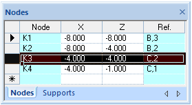
Add properties to the selection of a single node or a set of nodes with one command. Click on a node to make it selected (hold Shift key to select a group of nodes). Another way to select a node(s) is to define a selection area by dragging the mouse pointer around the specific nodes or to select nodes in the grid:
The selected nodes are colored red (by default) in the graphical area
|
Previous view of the structure
Used to review isometric view of a structure
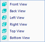
Projection planes of a structure:
Display freely rotated structure view: keep the left mouse button pressed down and move the cursor on the screen
Rotate the virtual structure forward by X axis
Rotate the virtual structure back by X axis
Rotate the virtual structure forward by Z axis
Rotate the virtual structure back by Z axis |
Structure input: |
|
|
Move releases along the entire length of the member
Split the members in place of intersections
Add internal objects (such as supports, releases, etc.) to the member without dividing it at the points of adding objects:
O1 - an internal support on a member without "Internal objects adding mode" O2 - an internal support on a member with "Internal objects adding mode"
Create properties on a region
Create properties on a polyline |
Create properties on a point
Open beam definition window
Define elastic foundation properties for members
Define a fixed support
Define rotation around local Y axis in a support
Define spring values in a support
Move support along member axis
Insert support inside the member by splitting it in to two members
Define rotational free connection (release) of a member
Define spring value for release connection |
Loads input: |
|
|
View or hide the Definition Window in Loads Generator
Set load's category to structural member(s) in Loads Generator. Every first use of this button (if structural member has no load's category) assigns to relevant member initial state consisting of selected load's category name and automatically recognized field and level numbers dependent on the structure design; every next use of this button with the same or different load's category will only update the existing category, but not the field and level
Set element's classification to structural member(s) in Loads Generator; available classifications:
If structural member was previously assigned to any element's classification, then every use of this button the existing classification will be updated to the new state
Set roof type to structural member(s) in Loads Generator. If structural member was previously assigned to any roof type, then every use of this button the existing type will be updated to the new state
Add dead load elements to structural member(s) in Loads Generator. Displayed load elements in Structure View layout directly depend on the values provided in the dead load elements choice grid. If the member is assigned to more than one dead load element, then every use of this button will add by one element to last existing |
Remove dead load elements from structural member(s) in Loads Generator. If the member is assigned to more than one dead load elements, then every use of this button will remove by one element from last existing
Remove level, field and category state from structural member(s) in Loads Generator
Update structural member(s) to higher by 1 field state in Loads Generator. If the member previously wasn't assigned to any field state, the Next Field button will be inactive to selected member
Update structural member(s) to lower by 1 field state in Loads Generator. If the member previously wasn't assigned to any field state, the Previous Field button will be inactive to selected member
Update structural member(s) to higher by 1 level state in Loads Generator. If the member previously wasn't assigned to any level state, the Next Level button will be inactive to selected member
Update structural member(s) to lower by 1 level state in Loads Generator. If the member previously wasn't assigned to any level state, the Previous Level button will be inactive to selected member
Define loads and load cases. Apply loads to nodes and members in the local or global direction
Define load combinations for ultimate limit state (ULS) and serviceability limit state (SLS) according to national codes
|
Results: |
|
|
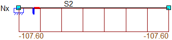
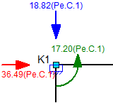
Display axial forces on the structure (in brown color by default)
Display biaxial normal forces / principal biaxial normal forces on the structure (in brown color by default)
Display shear forces on the structure (in blue color by default)
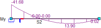
Display bending/torsional/principal moments on the structure (in purple color by default)
Reinforcement moment for the benefit of the required reinforcement at the top/bottom side in the X' or Y' direction [kNm/m]
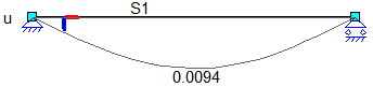
Display nodal displacements on the structure
Display stresses on the structure
Set filter to sigma stresses
Apply some polygonal zone with predefined local directions |
Display support reactions (shape X, Y, Z, Xr, Yr, Zr) on the structure
Display soil pressure on the structure
Apply multi-layer principal and/or secondary reinforcement on local direction zone(s) or the whole plate
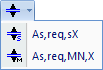
Required reinforcement in the local X’-direction [mm2/m]
Required reinforcement in the local Y’-direction [mm2/m]
Required reinforcement area at the bottom side in the X’-direction [mm2/m]
Required reinforcement area at the bottom side in the Y’-direction [mm2/m]
Required reinforcement area at the top side in the X’-direction [mm2/m]
Required reinforcement area at the top side in the Y’-direction [mm2/m]
Define value range of displayed results
Show/Hide linear elastic analysis results
|
Joint Connections: |
|
|
Print structure drawings including layout properties and preview
Print structure drawings as DXF files |
Display the Unity check chart or M-Phi diagram in relative units
Display the Unity check chart or M-Phi diagram in absolute units |
Concrete: |
|
|
Set concrete properties (such as deflections and displacements) to the structure
Add pile to the foundation plan
Display axial forces on the structure (in brown color by default)
Display shear forces on the structure (in blue color by default)
Display bending moments on the structure (in purple color by default)
Display support reactions (shape X, Z, Yr) on the structure |
Manage grid lines. Automatically apply grid lines to the structure or manage them manually
Automatically generate dimensions on the whole structure
Delete automatically generated dimensions on the whole structure |
Steel: |
|
|
Set steel check properties (such as cross check, lateral buckling, buckling, deflections, fire protection) to the structure
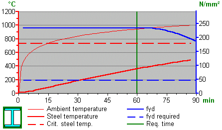
Graphical representation of the fire protection analysis results
Graphical representation of the fire protection analysis results |
Graphical representation of the fire protection analysis results (Fyd diagrams)
|
Timber: |
|
|
Set timber check properties (such as cross check, lateral buckling, buckling, deflections, fire protection) to the structure |
|


 As;req X:
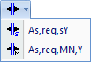 As;req Y: