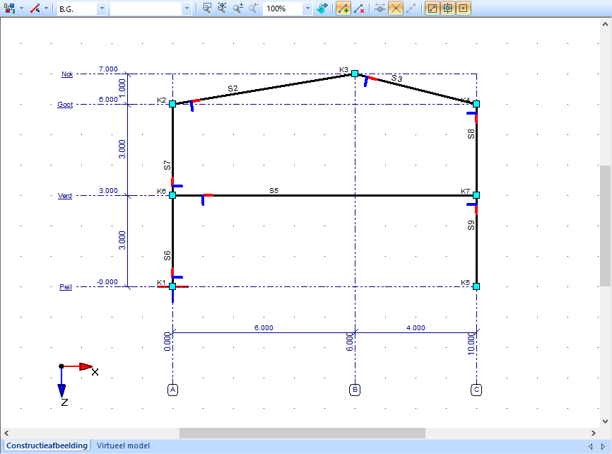
A structural element in a member model consists of a member with a node at the start (node B) and a node at the end (node E). Nodes and members can be created in two ways:
Manual entry: Enter the coordinates of each node in the "Nodes" grid, then manually define members connecting two nodes.
Free sketching: Draw nodes and members directly with the mouse, using the snap functions to align with grid points, grid lines, or existing nodes and members.
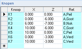
Details of nodes:
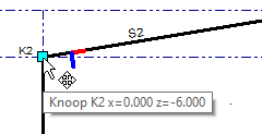
Button label: Displays a prefix “N” followed by a serial number.
Coordinates: X and Z values (for a 2D-Frame).
Reference: If a node coincides with a grid point, this is indicated in the Ref. column.
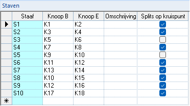
Details of members:
Member label: Displays a prefix “M” followed by a serial number.
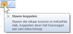
By enabling the checkboxes for at least two intersecting members, a node is created at the intersection without splitting the members into separate structural elements (unlike the "Split members" function).
If one of the intersecting members is not selected, no intersection node is generated.
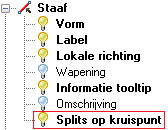
To display nodes created with "Split on intersection", the "Split on intersection" layer must be activated in the "Visibility options":
Add, remove and change nodes and members
Functions:
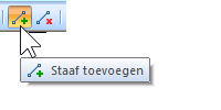
Add member: Command to add nodes and members to the model.
Remove member: Command to delete a node or a member. If multiple nodes and/or members are selected, all selected elements will be deleted.
Special functions:
Split members: Intersecting members are automatically divided and a node is created at each point of intersection.
This function is controlled by an on/off toggle.
By default, the toggle is on.
If the toggle is off, intersecting members are not automatically connected.
Connecting members manually:
Two members can be linked afterwards.
Select both members, activate the "Split members" toggle, and confirm the connection.
Special functions:
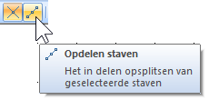
Divide members:
Function: A member can be divided into multiple nodes and bars after it has been created.
Activation: When a member is selected, the "Split members" button becomes active.
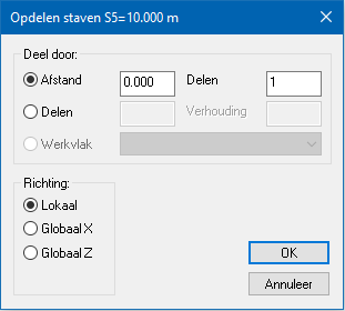
Procedure:
Distance and divisions:
Enter the distance from the start node (Node B) and the number of divisions.
If the number of divisions is greater than 1, the division is repeated at the same distance along the member.
Direction:
By default, the distance is measured along the local member axis.
Optionally, the distance can be applied in the global coordinate direction.
Resulting division:
The member is split into X equal parts according to the specified distance and number of divisions.
Selections and functions via the right mouse button
Additional functions for modifying and editing analysis models are available via the right mouse button.
These functions can be applied to:
Individual nodes and members, or
Groups (selections) of nodes and members.
Because many of these functions operate on groups, the "Selection" function is explained first:
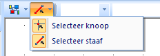
Selection filters:
By default, both nodes and members are selectable.
If desired, you can disable one of the two options to restrict the selection to either nodes or members only.
Selection options:
Single selection: Click on a node or member to select it. Selected elements are highlighted in red.
Multiple selection: Expand the selection by clicking on additional nodes or members while holding down the Shift or Ctrl key.
Frame selection (window):
Draw a frame from left to right:
Press and hold the left mouse button at the starting point on the left of the area you want to select.
Drag the mouse toward the right while holding the button.
Release the mouse button to complete the selection.
Only nodes or members completely inside the frame are selected.
The frame is displayed with a solid line.
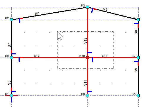
Frame selection (crossing):
Draw a frame from right to left:
Press and hold the left mouse button at the starting point on the right of the area you want to select.
Drag the mouse toward the left while holding the button.
Release the mouse button to complete the selection.
Nodes or members fully or partially inside the frame are selected.
The frame is displayed with a dotted line.
These selection methods can be used simultaneously.
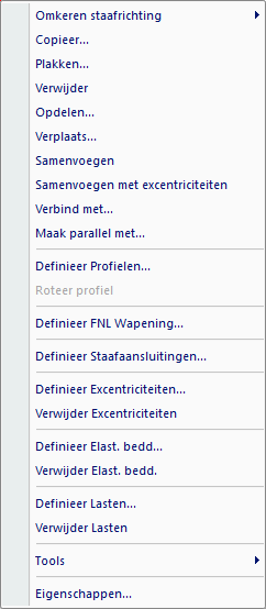
Right mouse key functions:
Reverse member direction: Changes the local orientation of a member. Reversing can be done according to either the local or global orientation.
Local: the start node (B) and end node (E) are swapped relative to the member itself.
Global: the start node (B) and end node (E) are swapped considering the main global directions.
Note: Reversing member direction can significantly affect any already applied loads.
Copy: Copies the selection, using a reference point at a node or a coordinate. The copied selection can then be pasted relative to the chosen reference point.
Paste: Pastes the copied selection at a chosen node or coordinate.
Delete: Deletes the selected nodes or members.
Divide: Splits a selected member into multiple members, with either equal or unequal lengths.
Move: Moves the selected nodes or members by a relative or absolute distance.
Merge: Merges multiple collinear members into a single member.
Merge with eccentricities
Connect to: Extends a member to a designated member, creating an intermediate node at the intersection.
Make parallel with: Rotates a member so that it becomes parallel to a designated member. The start node (Node B) remains in its original position.
The other functions provide shortcuts to topics that are covered in the relevant chapters.