
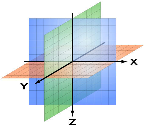
MatrixFrame® uses an X-Y-Z coordinate system, with the positive Z-axis pointing downwards. The arrows in the figure below indicate the positive directions of the X, Y and Z axes.
This X-Y-Z coordinate system is used throughout all modules, including 1D beams, 2D grillages, 2D and 3D frames, as well as FEM models. The same coordinate system applies to both the global coordinate system and the local coordinate systems of individual structural elements, such as members and plates.
Rotations
The figure below illustrates the directions of rotation. The colors used for the directions correspond to the RGB color scheme: X = red, Y = green, and Z = blue.
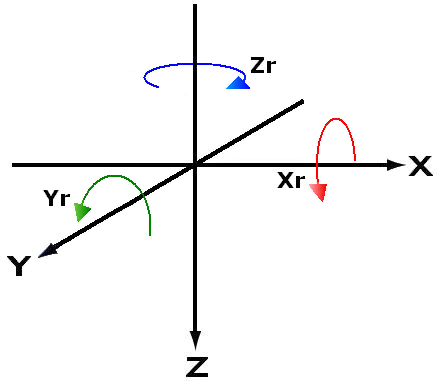
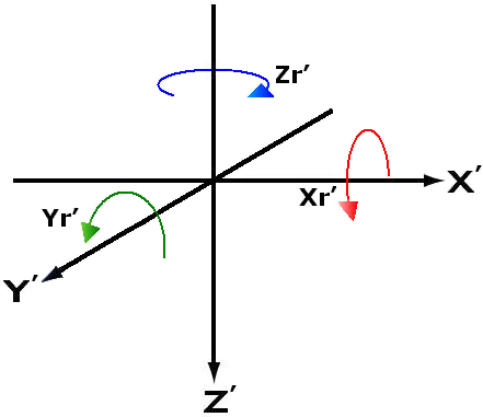
These directions also apply to the local coordinate system, i.e. the coordinate system assigned to an individual structural element (member or plate). Local coordinate axes are indicated with a prime symbol (′): X′, Y′, and Z′. The corresponding local rotation directions are denoted as Xr′, Yr′, and Zr′.
Right-hand rule
The global and local coordinate systems follow the right-hand rule, both for axis directions and for rotations.
Use the right-hand rule to determine the positive directions of the X-, Y-, and Z-axes:
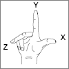
- Make a fist with your right hand.
- Extend your thumb in the direction of the positive X-axis.
- Extend your forefinger; this indicates the positive Y-axis.
- Extend your middle finger perpendicular to the thumb and forefinger; this indicates the positive Z-axis.
The right-hand rule is also used to determine the positive direction of rotation about each axis:
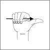
- Make a fist with your right hand.
- Point your thumb in the positive direction of the axis.
- The direction in which the fingers curl indicates the positive direction of rotation about that axis.
Forces
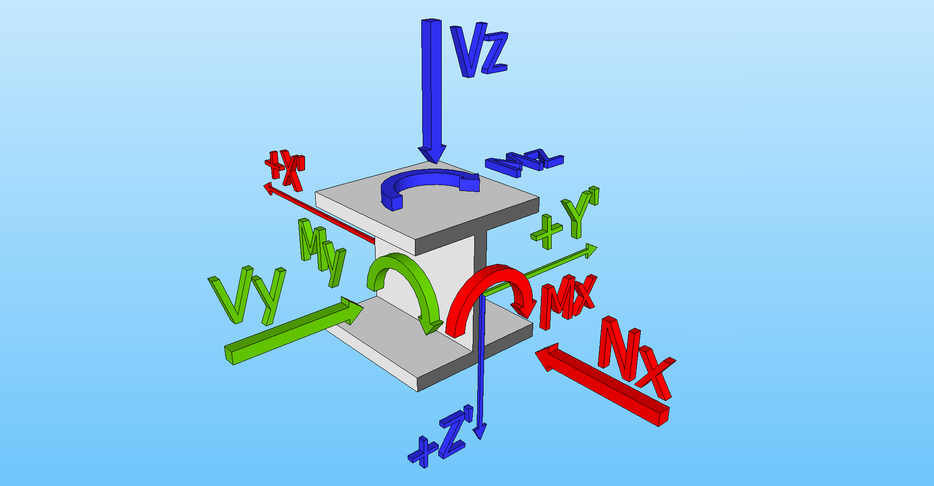
In the chapters on load input and calculation results, the force directions described below are of particular importance. The figure below illustrates the relevant force directions for reference:
Degrees of freedom
MatrixFrame® supports several project types (analysis models). Each project type is defined by a specific set of degrees of freedom:
Project type | Geometry | Loads | Mechanical results | ||||||||||||
| X | Y | Z | X | Y | Z | Xr | Yr | Zr | Mxx | Myy | Mzz | Vy | Vz | Nx | |
| 1D-Beam | + | - | - | + | - | - | - | + | - | - | + | - | - | + | - |
| 1.5D-Beam | + | - | - | + | + | + | + | + | + | + | + | + | + | + | + |
| 2D-Grillage | + | + | - | - | - | + | + | + | - | + | + | - | - | + | - |
| 2.5D-Grillage | + | + | - | + | + | + | + | + | + | + | + | + | + | + | + |
| 2D-Frame | + | - | + | + | - | + | - | + | - | - | + | - | - | + | + |
| 2D-Truss | + | - | + | + | - | + | - | + | - | - | - | - | - | + | + |
| 2.5D-Frame | + | - | + | + | + | + | + | + | + | + | + | + | + | + | + |
| 3D-Frame | + | + | + | + | + | + | + | + | + | + | + | + | + | + | + |
| 3D-Truss | + | + | + | + | + | + | - | - | - | - | - | - | + | + | + |
| 2D-Plate (FEM) | + | + | - | - | - | + | + | + | - | + | + | - | + | + | - |
| 2D-Wall (FEM) | + | - | + | + | + | + | + | + | + | + | + | + | + | + | + |