A calculation model (bar model) is schematized using nodes and bars. Nodes are defined by their coordinates, and bars form the connections between two nodes.
To simplify model input, grids can be used. The use of grids is optional, but in many cases it significantly facilitates and speeds up data entry.
There are two ways to work with grids:
- Predefined grids
Grids are defined in advance, after which nodes and bars can be placed by snapping to the grid using the snap function. - Automatically generated grids
The model is sketched directly at grid points, while MatrixFrame® automatically generates the corresponding grids. By assigning the correct grid dimensions afterwards, the calculation model can be created with fewer actions and accurate dimensions.
1. Manual definition of grid lines
Example:
Grid lines can be defined either relatively (intermediate spacing) or absolutely (fixed coordinates). This option can be selected when creating the grid lines:
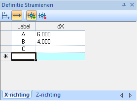 | Grid lines in the X direction with relative spacing |
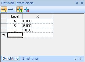 | Grid lines in the X direction with absolute coordinates |
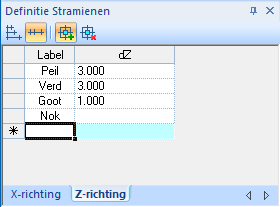 | Grid lines in the Z direction with relative spacing |
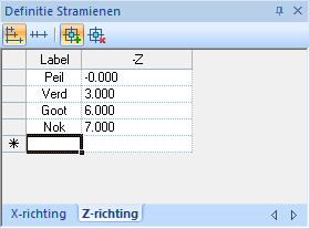 | Grid lines in the Z direction with absolute coordinates |
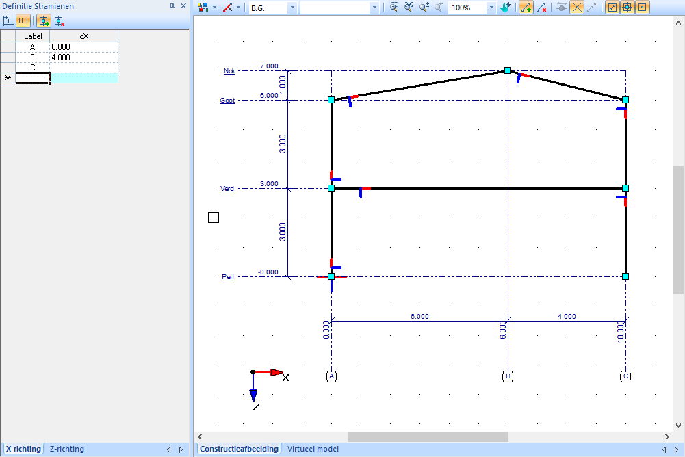
2. Automatic generation of grid lines
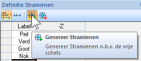 | Check that the automatic grid generation button is activated. By default, this button is turned on. |
Start by sketching the member model freely, clicking the start and end points of each member on the grid points. Ensure that:
Nodes that must be vertically aligned are positioned directly above each other.
Nodes that need to be at the same height are placed at the same horizontal level.
While sketching, MatrixFrame® automatically generates grid lines and dimension lines for the model. After completing the free sketch, grid line values can be adjusted in the “Grid lines” panel. As with manual grid entry, it is possible to choose between relative spacing or absolute coordinates for the grid lines.
Grid
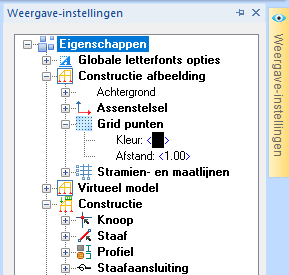 | The grid consists of points displayed in the graphical view of the structure. The appearance and behavior of the grid can be adjusted in the "Display settings", located on the right side of the screen:
|
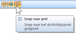 | Special functions:
These three options can be used independently of each other. |