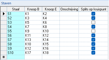
The “Split on intersection” tool allows control over how intersections in the structural model are handled. By enabling the checkboxes for at least two intersecting members in the “Split on intersection” column of the "Members" grid, a node is created at their intersection without splitting the members into separate structural elements.
This differs from the “Split members” tool ![]() , where intersecting members are automatically divided into separate members and provided with a node at the point of intersection. If the checkbox is disabled for one of the intersecting members, no intersection node is created.
, where intersecting members are automatically divided into separate members and provided with a node at the point of intersection. If the checkbox is disabled for one of the intersecting members, no intersection node is created.
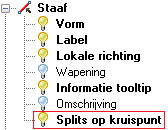
To display nodes created using "Split on intersection" on the structure, the “Split on intersection” layer must be activated in the "Visibility options":
2D-Frame
By default, 2D-Frame provides:
the “Split members” tool
 enabled;
the “Split on intersection” checkboxes in the "Members" grid disabled.
This configuration can be changed at any time if required:
1. Intersections can be created manually (when the "Split members" tool ![]() is disabled):
is disabled):
 | In the provided example, the only intersection is node K4. Nodes K2, K3, and K8 are not intersections; in this case, they only define the start and end nodes of members S1, S2, S5, and S6. |
2. Intersections can be generated automatically, with nodes created at the intersection points (when the "Split members" tool ![]() is enabled).
is enabled).
 | In the provided example, nodes K6, K2, K3, and K7 are intersections. |
3. Intersections can also be generated automatically using "Split on intersection", with nodes created at the intersection points, without dividing the members into separate structural elements:
| In the provided example, the structure is drawn with the “Split members” tool |
By default, 3D-Frame and 2D-Grillage provide:
| 3D-Frame | 2D-Grillage |
|
|
| This configuration can be changed at any time if needed. | |