
What is new in version 2027
Please be aware that you are using a beta version of the software. Although extensive testing has been done, users should exercise caution and maintain backups of all projects. Unexpected behavior may occur, and we encourage users to provide feedback for ongoing improvements.
General
The implementation of the Second Generation Eurocodes [G2] has been extended
The following calculations are now available in accordance with the Second Generation Eurocodes [G2]:
Code check of timber structures subjected to fire in accordance with EN 1995-1-2:2025.
Code check of concrete structures subjected to fire in accordance with EN 1992-1-2:2023.
Code check of concrete structures in accordance with EN 1992-1-1:2023#8.2.6 (Shear at interfaces).
Details are given in the MatrixFrame and MatrixTools sections below.
Important note: All Second Generation Eurocode calculations implemented in the software package – including corresponding UI options, tooltips, and informational reports – are explicitly marked with the “[G2]” tag. Any options or reports without this tag refer to the current (first-generation) Eurocode normative documents. Results obtained under [G2] may change between versions.
[G2] A separate reference age tref governing the development of concrete strength has been introduced
Previously, the concrete age specified for creep calculation (t0) also controlled the development of concrete strength and bond strength; therefore, changing the creep age affected the strength properties. A separate reference age, tref, now governs strength development independently. Calculation results may differ from previous versions whenever tref is not equal to the creep age previously used for both.
The cold-formed hollow sections database has been updated
The database has been updated to reflect the requirements of EN 10219-2:2019 for cold-formed square and rectangular hollow sections (inner and outer corner radii) and has been expanded with additional profile sizes.
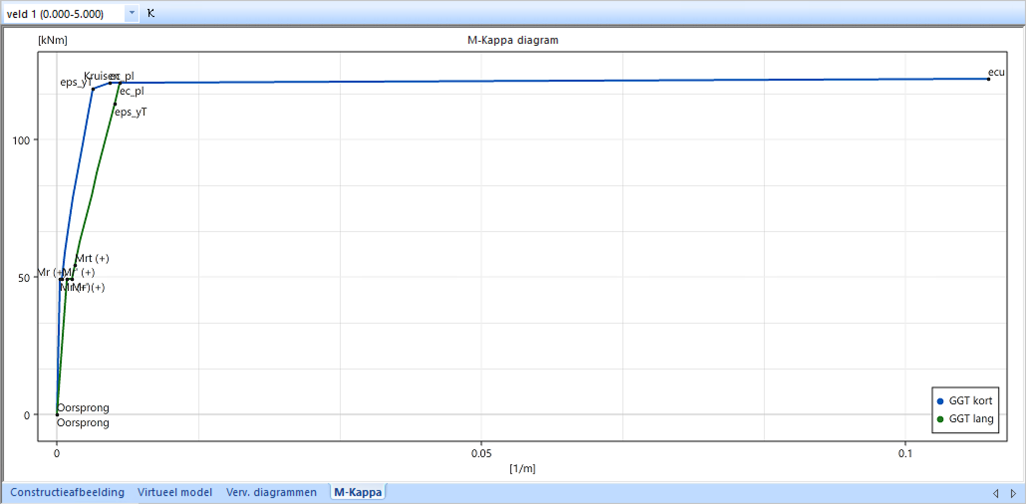
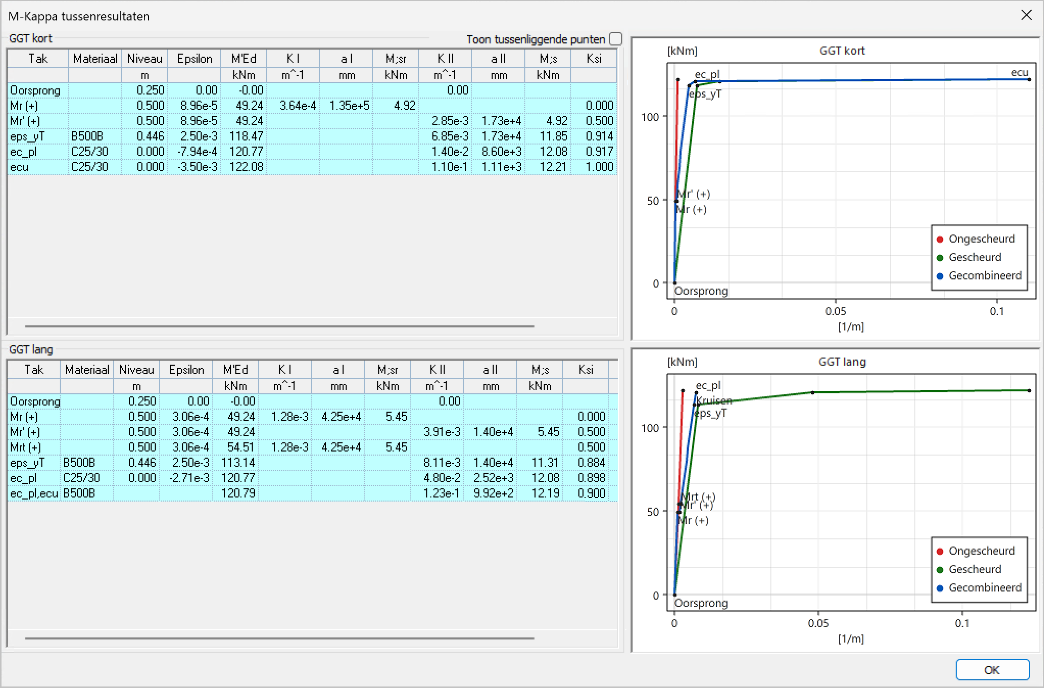
The M-N-Kappa diagrams have been redesigned across all packages
The M-N-Kappa diagrams in MatrixFrame, as well as in the Concrete Toolbox and Section Editor within MatrixTools, have been redesigned for better visibility on screen and in printed reports, effectively defining and highlighting the key decision points.
MatrixFrame
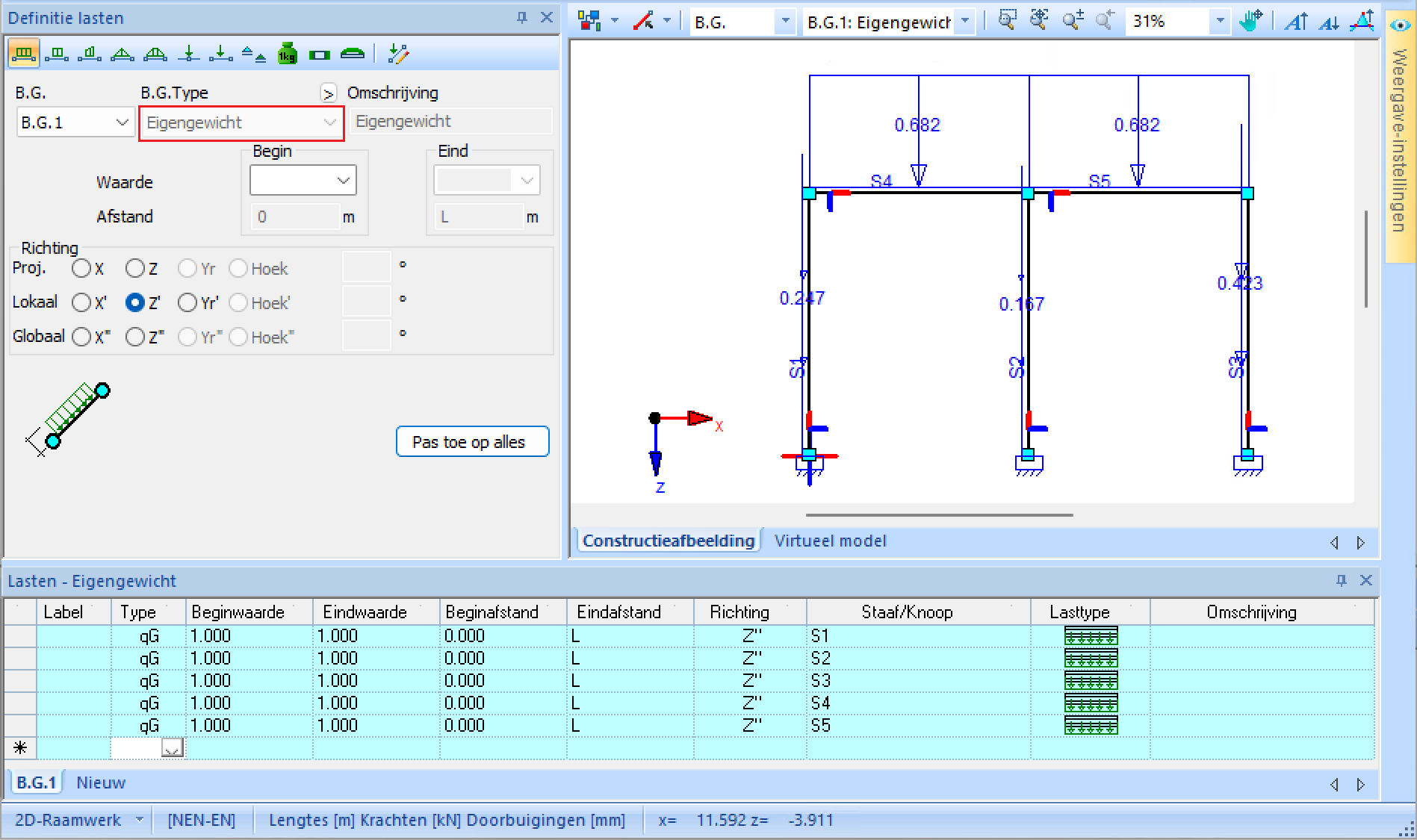
A Self-weight load case has been introduced
A load case can now be assigned the 'Self-weight' type. Previously, a self-weight load had to be placed on each member separately, and it did not automatically adapt to subsequent changes in the model. Once a load case is designated as 'Self-weight', self-weight loads are generated for the entire structure and dynamically kept up to date as members are added or removed. These generated loads are displayed as read-only, as they are directly derived from the sections and materials.
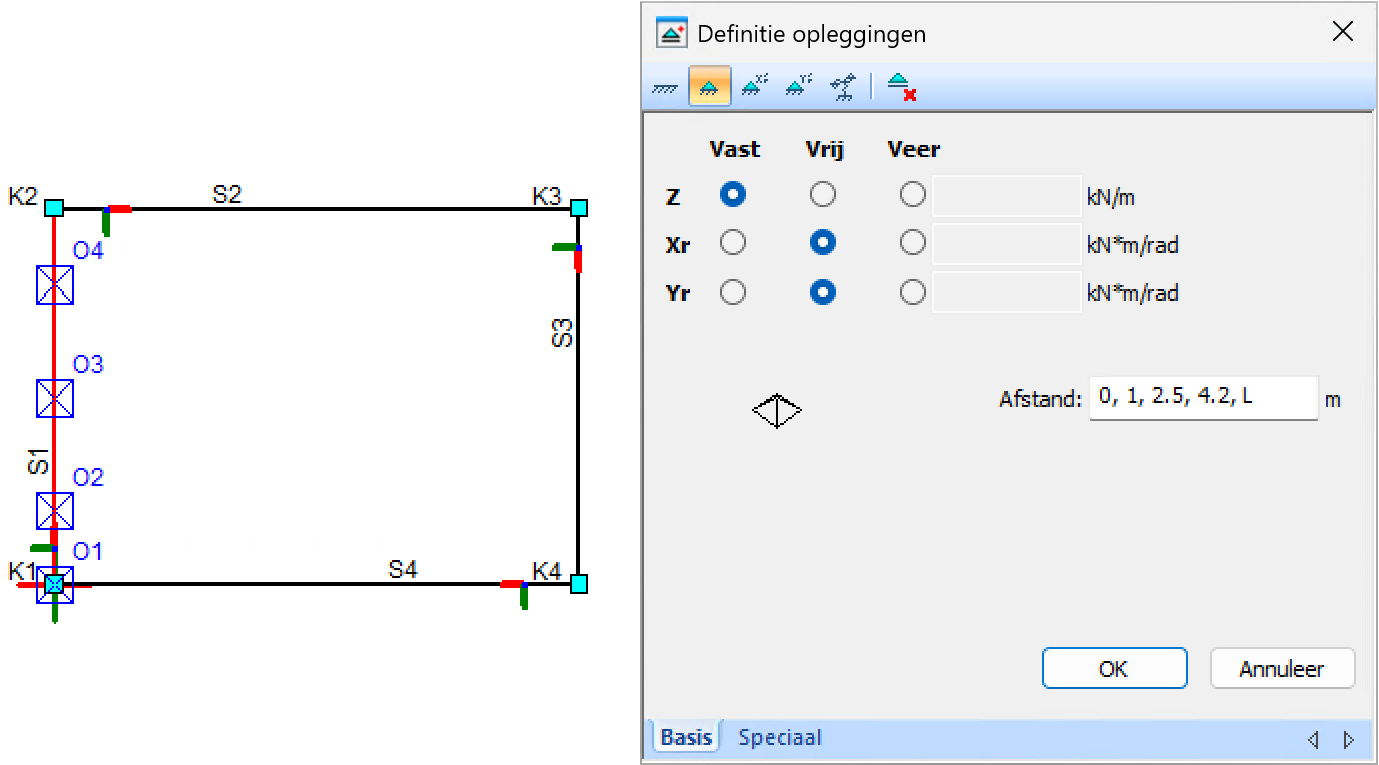
Multiple supports can be added to a member at once
When a member is selected, the Right-click → Add Supports function for a Grillage now accepts multiple support positions at once. You can enter multiple distances as comma-separated values. The notation “L”, representing the total member length, is also accepted as an input value. This functionality mirrors how lateral supports are defined in the steel module, significantly speeding up the definition of several supports along a member.
Stability (F-Euler) analysis: multiple modes and out-of-plane modes for 2D Frame structures
The number of stability modes to be calculated can now be set from 1 to 10 (the default is 1). For 2D Frame structures, an additional option allows stability modes to be calculated either exclusively within the plane of the structure or both in-plane and out-of-plane.
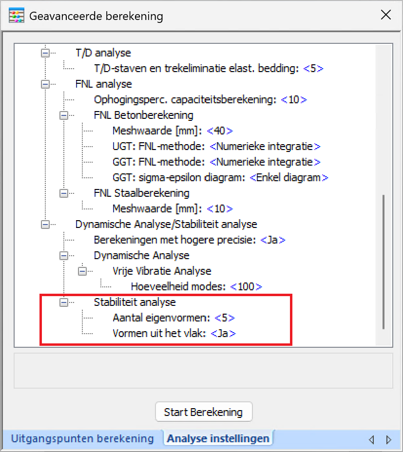
When out-of-plane modes are evaluated, each result is labeled with an 'In-plane: yes/no' indicator:
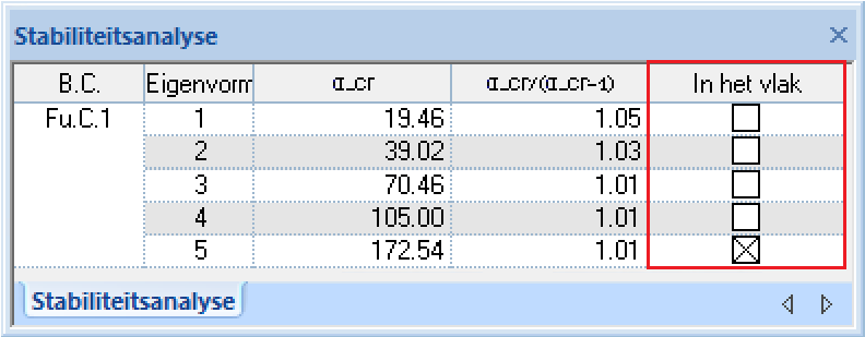
With the visualization of the F-Euler Analysis option enabled, the report displays the stability modes of a 2D Frame structure in an isometric view, making out-of-plane instability modes clearly visible.
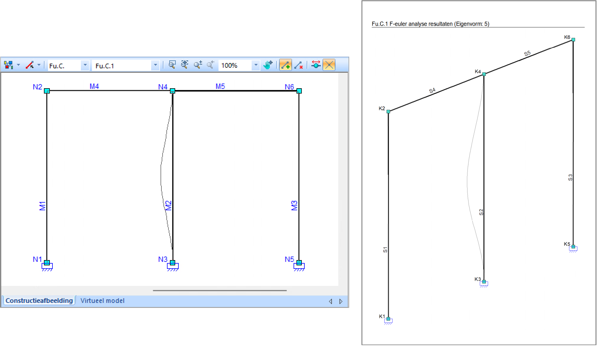
Modal (Eigenfrequency) analysis: detailed mode shapes and a Higher-precision calculations option
The deformation shape (eigenform) for every calculated eigenfrequency is now generated in detail and can be visualized. Previously, the shape was only approximated because members were internally divided into just two segments. The new Higher-Precision Calculations option in the Analysis Options divides members into six segments, resulting in noticeably smoother mode shapes. This option replaces the previous stability-only setting and applies to both the dynamic and the stability analyses.
Results: L/x and H/x ratio for deflection representation is introduced
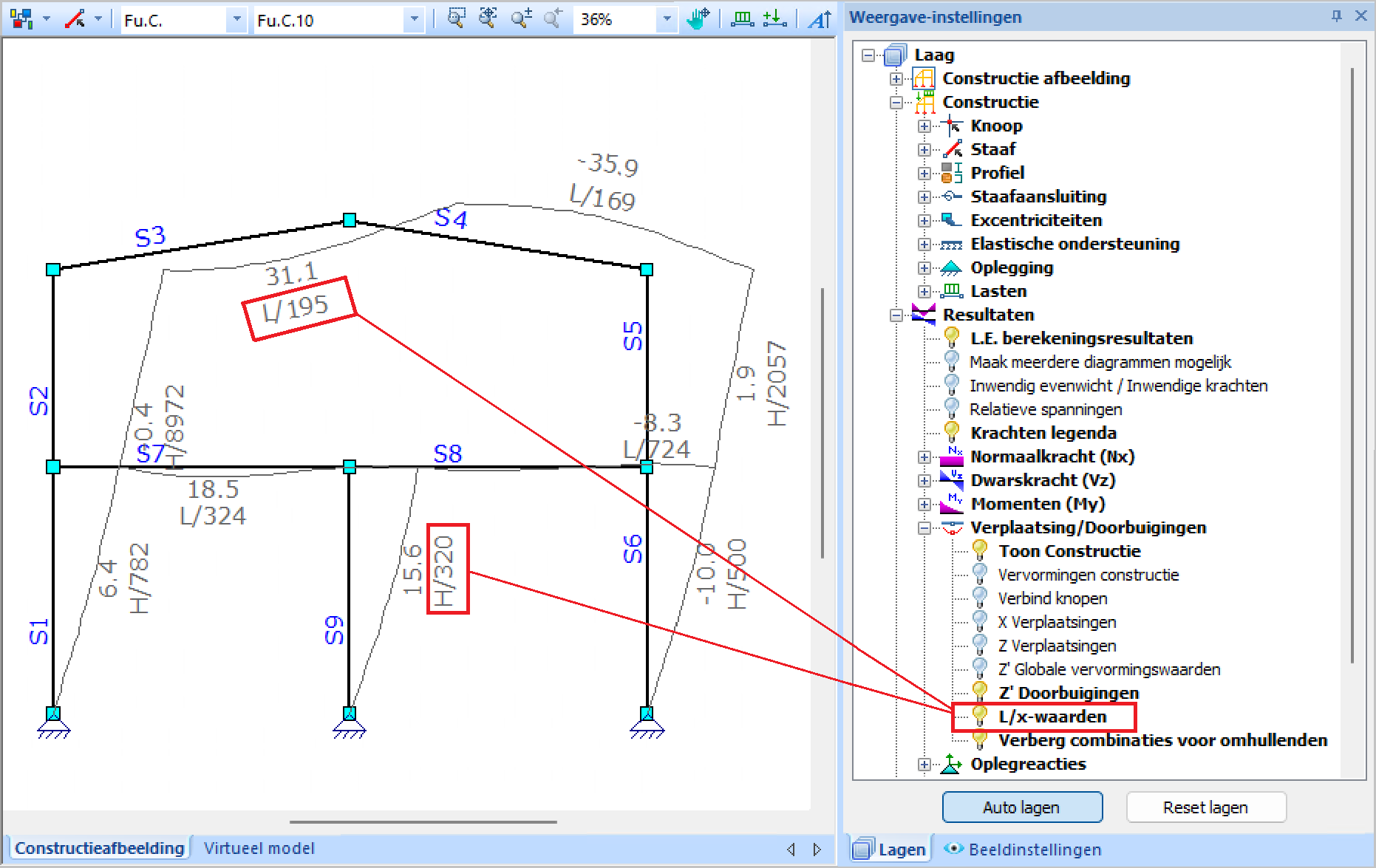
The deflection values on the drawing gave no indication of the span they belong to. A new 'L/x values' layer under Displacements/Deflections, off by default, writes the L/x ratio under each field's largest relative deflection, or H/x on a vertical member, using the support span that deflection is measured on.
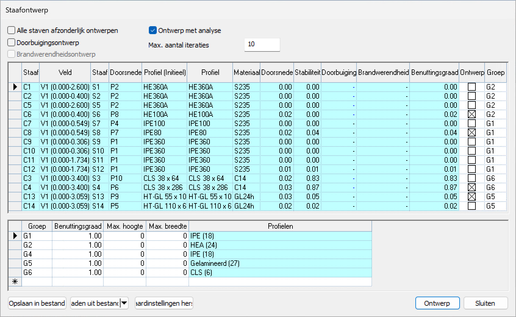
A unified Member Design feature for steel and timber members has been introduced
The "Member Design" dialog has been completely redesigned into a single, unified command that applies to both steel and timber members simultaneously. This feature provides tools to optimize and design cross-sections for any mix of steel and timber members in a single calculation run, based on user-defined groups and specific design criteria (such as utilization targets, deflections, and fire resistance). For more detailed information and configuration steps, see: Member design.
Steel: lateral-torsional buckling length from a buckling length factor
Previously, the buckling length for the lateral-torsional buckling check could only be derived from the member's lateral supports. The steel settings now let you choose between lateral supports and a lateral-torsional buckling length. With the latter method, a buckling length factor (β) can be specified separately for the top and bottom flanges, with the buckling length calculated as Lcr = β·L. Existing projects retain the lateral supports method, ensuring their calculation results remain unchanged.
[G2] FEM plates and walls: concrete shear check using the shear in both directions
Under [G2] EN 1992-1-1:2023, the out-of-plane shear resistance of FEM plates and walls is now verified using the combined biaxial shear forces, as required by the second-generation Eurocode.
2D FEM plates: Top/Bottom reinforcement regions on new area contours
Previously, when a reinforcement position was set to Top/Bottom, drawing a new area contour created only a single reinforcement region instead of separate Top and Bottom regions. Consequently, the SmartSense Reinforcement grid displayed only one row instead of the expected two, even though applying the same preset to an existing area functioned correctly. Drawing a new contour now properly splits the Top/Bottom setting into separate Top and Bottom reinforcement regions – matching how presets are applied elsewhere – and the grid consistently displays both rows.
Concrete options: project-wide defaults moved out of the FEM section
The FEM section under Concrete Options previously contained several settings that apply to the entire project rather than being specific to the FEM analysis, such as the reinforcement steel grade, structural and exposure classes, aggregate size, and concrete age. Because the FEM Section is only accessible in FEM Plate projects, these defaults could not be viewed or modified in other project types. These settings have now been moved to Concrete defaults, making them accessible and editable across all project types. Consequently, the FEM section now contains only settings specific to the FEM Plate analysis.
Torsional reinforcement is aligned with torsional effects along the member
The calculation and placement of the required torsional reinforcement have been revised. Previously, torsional reinforcement was distributed uniformly over the entire member based on the maximum required reinforcement, resulting in the same arrangement along its whole length. The placement now accounts for the actual distribution of torsional effects along the structural member, optimizing reinforcement efficiency.
The concrete General data report has been split into three sections
To simplify its structure, the concrete General data report has been divided into three separate sections: General, Supports, and Creep. Each section can now be included and displayed independently, based on the active settings.
Concrete reports: reinforcement bars retain configured display colors in report images
Previously, reinforcement bars selected in the model were displayed in the selection color (red) within report images, even though these images should be generated without active selections. This issue has been resolved; the top and bottom bar positions now ignore the selection state during report generation, ensuring all bars are rendered in their configured display colors.
Concrete settings: the Zi option has been renamed, and the Stirrups option clarified
The option previously called Advanced Z calculation has been renamed to better reflect its function: it defines the lever arm Zi used in the shear code check. Enabling this option (when set to 'Yes') determines Zi from the internal force equilibrium calculation, while disabling it (when set to 'No') determines Zi based on 0.9d. This option does not affect the MRd or As,req calculations.
Additionally, the Stirrups option tooltip on the Prefab tab now clarifies its structural behavior. When enabled, stirrups are distributed over the entire section height, including both the top and bottom concrete layers. When disabled, stirrups are arranged only within the top concrete layer. This setting can significantly affect the shear check, as Zi may vary considerably depending on whether it is calculated from the top layer only or from the full section height.
Shear verification without shear reinforcement (NEN-EN National Annex): aggregate size sourced from Agg.Dlower
Previously, in the shear verification of concrete members without shear reinforcement according to the NEN-EN 1992-1-1 National Annex, the aggregate size parameter was incorrectly taken from Nom.agg instead of Agg.Dlower, as required by the design code. This has been corrected: the aggregate size is now determined from Agg.Dlower, which is available as an input parameter. Consequently, calculation results for this shear verification may change.
Concrete wizard: configured settings retained during bar position recalculation
The settings configured within the wizard (such as combined bars, trading length, curved anchorage, and hairpins) are now retained when bar positions are recalculated – for example, after modifying the reinforcement at a specific position. Previously, these settings were reset, and combined bars were split up again.
When the trading length option is enabled, bars longer than 14 meters are no longer cut and are kept as a single continuous bar. Prior to this fix, a segment of such a bar could be erroneously omitted, leaving a section of the beam without basic reinforcement on the drawing. For projects utilizing the trading length option on beams exceeding 14 meters, it is highly recommended to rerun the wizard and verify the drawings. Additionally, the Max. lap option has been removed from the wizard.
Concrete bar placement: corrected bar positions and lengths
Several corrections have been made to the placement of reinforcement bars:
Previously, additional reinforcement above the supports could be off-center and either too long or too short on certain beams – especially those drawn from right to left. This reinforcement is now properly centered over the supports and features the correct length.
Additional reinforcement bars on beams that start partway along a member now end at the correct position (the point where they are no longer theoretically required plus the anchorage length). Previously, these bars could erroneously extend to the end of the member; while structural safety was maintained, bar lengths were often overestimated.
In members featuring more than one cross-section type, the range used for the bottom bar positions was determined incorrectly, resulting in bars generated with incorrect lengths. The bottom bar positions now correctly cover the intended part of the member.
In 3D structures (such as grillages), bars meeting at an angle could be incorrectly joined into a single structural member because the continuity check ignored one of the three spatial directions. All three directions are now taken into account, ensuring that structural members are defined correctly.
Concrete fire check: shear force sourced from the correct side on reversed members
Previously, for members whose start and end points were defined in the opposite order – causing the local axis to be oriented in the opposite direction – the shear fire check incorrectly used the accidental shear force (Vz) from the wrong side of the cross-section. This issue has been resolved: the check now uses the shear force from the correct side. Prior to this fix, forces from the opposite side were evaluated (swapping the left and right positions), which affected the fire check results for these specific members.
Steel connections: member labels in the virtual model are independent of zoom
Previously, member labels in the virtual model view were tied to the model zoom, causing them to become disproportionately large and obscure the connection itself. These labels are now independent of the model zoom and can be resized separately using Ctrl + mouse wheel, mirroring the functionality of the drawing view.
MatrixTools
[G2] Concrete Toolbox: cement class and concrete age at loading
All Concrete Toolbox documents now allow the input of the cement class and the concrete age at loading. The factors kt,c and kt,t for sustained loading are automatically calculated from these values. Previously, these factors were fixed (kt,t = 0.8). Consequently, calculation results under the second-generation Eurocode [G2] may change, and it is recommended to re-verify existing designs. Designs complying with the first-generation Eurocode remain unaffected.
[G2] Point-supported plate and Line-supported plate
The Point-supported plate and the Line-supported plate components have been updated to comply with the calculation procedures and design provisions of the second-generation Eurocodes.
Cross M+N: consistent reinforcement drawing
The reinforcement drawings for the All-sided and Two-sided layouts no longer differ by moment axis. Calculation results remain unaffected.