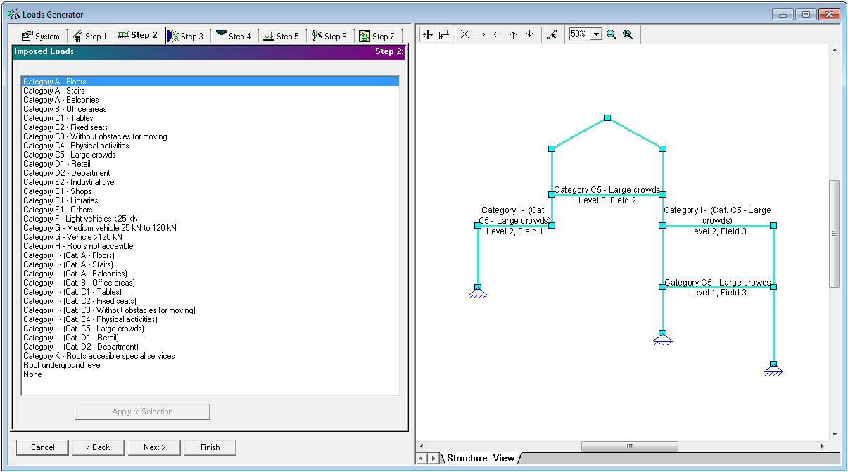
Fig 1. Loads Generator Step 2: Imposed Loads
Loads Generator provides an internal/automatic function to recognize imposed loads of structural elements. Recognition results are represented on Structure View with possibility to add/remove/change imposed loads categories or to move structure fields and levels.
With the imposed loads generator one Imposed load can be defined from the beginning till the end of the beam and it can be divided automatically into load cases specialized for separate floor fields. These Load Cases are necessary to define load combinations whether they are loaded or unloaded (Combination Generator).
A floor field is the area between two supports or between not supported end of beam and support (cantilever). A beam which consists for example four supports is divided into three floor fields and a beam which consists six supports is divided into five floor fields.
In case of alterations in the number of supports and the type and position of the supports, the floor fields will be modified automatically and the load cases will be generated again.
Generation of imposed loads on the elements requires preset of Category of loaded area (EN 1991-1-1, NEN-EN 1991-1-1 tables 6.2-6.10) as subset of Category of use (EN 1991-1-1 table 6.1). Preset of Category of loaded area generates characteristic value of a uniformly distributed load qk [kN/m2] and characteristic value of a variable concentrated load Qk [kN] in a range of minimal, maximal or default (underlined) values as described in EN 1991-1-1, NEN-EN 1991-1-1 tables 6.2-6.10. In addition to the value qk mentioned in the EN 1991-1-1, NEN-EN 1991-1-1 table 6.2, self-weight of movable partitions could be added (EN 1991-1-1#6.3.1.2(8) ).
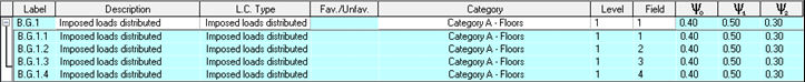
Preset of Category of loaded area as subset of Category of use generates Recommended values of ψ factors (EN 1990#A1.2.2 (Table A1.1), NEN-EN 1990#A1.2.2 (Table A1.1) ) is used for generation of load combinations.
The characteristic values for variable loads for buildings, are generally based on a design working life of 50 years. If design working live is different from the design working life of 50 years, the characteristic values of the variable uniformly distributed loads should be adapted. Individually factor ψ1 in combination with defined reference period) is used for adoption of the characteristic values of the variable uniformly distributed loads defined in NEN-EN 1990#A1.1(2).
Working example:
Calculation presumptions according to NEN-EN 1991-1-1:
Category of use : A - Areas for domestic and residential activities
Subcategory : A - Floors
Mobile partitions (in addition) : N/A
Reference period : 30 years
Generator calculation result:
0,97(Cprob NEN-EN 1990#A1.2.2 (Table A1.1)) x 1,75(qk NEN-EN 1991-1-1#6.3.1.2( table 6.2)) x 9 (system length) = 15,30 kN/m
Result of load generator – four load cases, separately for each supports determinate loaded field:
Quantity of load cases determinate of loaded fields is dynamically changing by changing of quantity of supports and/or placement of load along the beam. Such a dynamical changing of load cases (loaded fields) should be attended by user and is notification guided.
Generated loaded areas as fields persist in load combination generator: