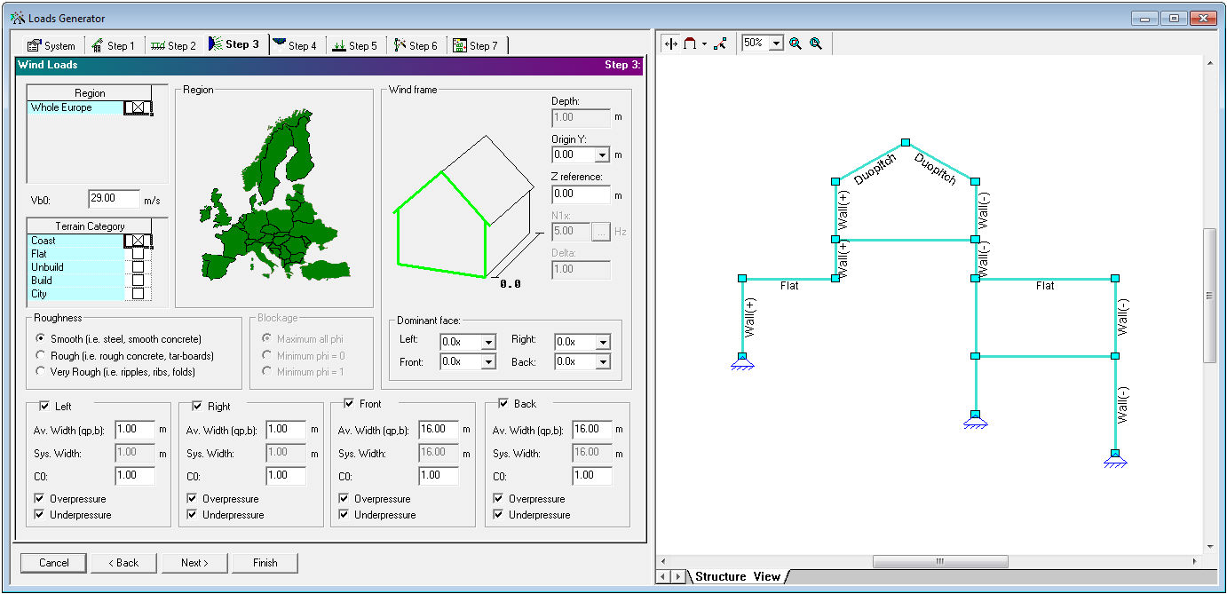
Fig 1. Loads Generator Step 3: Wind Loads
Loads Generator recognizes wind impact on structural elements. User is expected to define parameters for the wind loads calculation.
Available wind geographical zones are presented in Region grid. Selected zones are shown on Region map. Belonging on the regions terrains are listed in selectable Terrain Category grid and must be selected too.
Vb0 is fundamental value of basic wind velocity [m/s].
Surface roughness:
- Smooth surface
- <=40 mm - small roughness
- >40 mm - rough surface
Blockage part describes degree of blockage under canopy roof:
- maximum all phi
- minimum phi=0 represents an empty canopy
- minimum phi=1 represents the canopy fully blocked with contents to the down wind eaves only
Wind direction in respect of building (from left, from right, from front, from back) with parameters:
|
Parameter |
Description |
|
Average width (qp, b) |
average width value [m] is used for calculation of qp (in the EN and EN-National code mentioned as b, in NEN6702 mentioned as Pw) and CsCd. This parameter indirect describes blown surface |
|
System width |
value describing distance [m] between the frames (see System) |
|
C0 |
orography factor with default value 1.00 |
|
Overpressure |
wind pressure from inside (negative internal pressure) |
|
Underpressure |
wind pressure from outside (positive internal pressure) |
Wind frame parameters:
|
Parameter |
Description |
|
Depth |
structure depth (length of surface parallel to the wind direction) [m] |
|
Origin Y |
origin [m] by Y axis for determining wind frame in structure; origin Y parameter depends on System length (L) and Frames count parameters (see System) |
|
Z reference |
reference height for determining the structural factor [m] |
|
N1x |
fundamental frequency of along wind vibration [Hz]; N1x cell may be disabled and calculated automatically because of structure height h < 15 m
N1x frequency calculation is possible in case all of the following conditions are satisfied:
|
|
Delta |
logarithmic decrement of damping; Delta cell may be disabled and calculated automatically because of frequency N1x >= 5 Hz |
|
Dominant face |
left, right, front, back: 0.0x - for buildings without a dominant face 2.0x - for buildings with a dominant face, when the area of the openings (open spaces through which the wind enters the surface) at the dominant face is twice the area of the openings in the remaining faces 3.0x - for buildings with a dominant face, when the area of the openings (open spaces through which the wind enters the surface) at the dominant face is at least 3 times the area of the openings in the remaining faces |