Isoline view
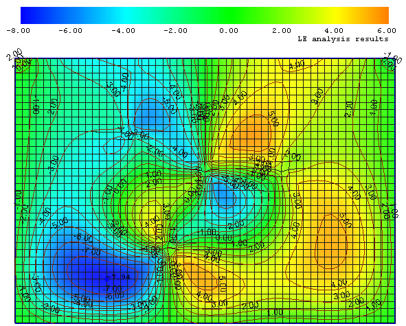
The plate analysis results (deflections, stresses, forces, support reactions, moments) are represented in an isoline view. Isoline view is a scale model of the three-dimensional plate surface, represented on the two- or three-dimensional plane through the use of isolines. An isoline of a function is a curve along which the function has a constant value. An isoline connects all points where the function has the same particular value:
Centroid points
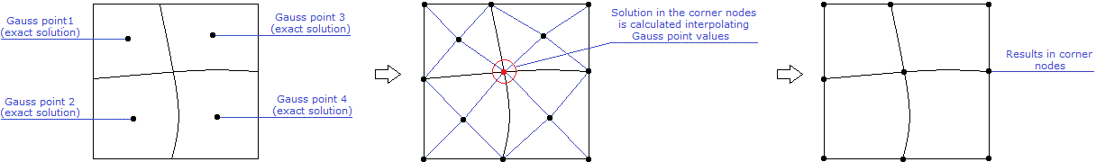
The exact solutions of forces/stresses/reactions are calculated in Gauss centroid points (geometric centers) of every mesh element area, while exact solution of displacements is calculated for the corner nodes of FE. For representation compatibility forces/stresses/reactions results are recalculated to the nodal form as following:
Isoline rules
1. Every point on a given isoline is of the exact same value; that is, isolines connect points of equal value.
2. Isolines always close to form an irregular circle; but sometimes part of an isoline extends beyond the plate area, so that you cannot see the entire line:
3. The distance between any two adjacent isolines is the isoline interval (the isolines generally have values printed on them). The values are calculated by dividing the distance between the maximal and minimal values (shown on the scale) of the analysis results to equal intervals.
 |
 |
4. Isolines never cross one another.
5. Isolines never split.
6. Evenly-spaced isolines represent a uniform slope. Closely spaced isolines indicate a steep slope. Widely spaced isolines indicate a gentle slope, i.e., the spacing of the isolines indicates the gradient/slope.
7. A concentric series of closed isolines represent an elevation:
8. In cases where slope orientation changes, isolines of equal elevation will be repeated.
9. The gradient of the calculated function is always perpendicular to the isolines.