Creating new plate supports or changing their properties is performed by Supports definition ![]() :
:
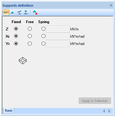
![]() Define fixed support
Define fixed support
![]() Define free rotation for support
Define free rotation for support
![]() Define spring values for supoort
Define spring values for supoort
![]() Delete supports
Delete supports
When combined with the following geometry design objects in Structure View, loads are applied as area, polyline or point:
![]() Create region (supports on a region)
Create region (supports on a region)
![]() Create polyline (supports on a polyline)
Create polyline (supports on a polyline)
![]() Create point (supports on a point)
Create point (supports on a point)
By pressing a button for plate geometry design object to be added, the default boundary condition respectively to the geometry object is generated. For a supported region it is Z(Fixed)/Xr(Fixed)/Yr(Fixed), for a polyline - Z(Fixed)/ Xr(Free)/Yr(Free) and for a point object - Z(Fixed)/Xr(Free)/Yr(Free).
Boundary conditions (supporting conditions) are changed by making appropriate settings to define possible degree of freedom, respectively in Z, Xr and Yr directions. After defining boundary conditions of supports they can be applied to selection.
Supports properties are also displayed in "Plate definition" tree ("Supports" branch):
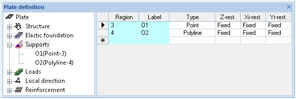
- Region - refers to the designed region of the plate containing a unique boundary condition set. The region itself is described in the lower branch(es) of the "Supports" tree;
- Label – refers to the unique boundary conditions set of a support;
- Type – refers to plate geometry design object type (region, polyline or point) on what boundary condition is applied;
- Z-rest. – refers to the boundary condition of a support in a global Z direction. It could be defined as "fixed", "free" or some value as 0 < value < 1e111, defining elastic spring;
- Xr-rest. – refers to the boundary condition of a support in a global Xr direction. It could be defined as "fixed", "free" or some value as 0 < value < 1e111, defining elastic spring;
- Yr-rest. – refers to the boundary condition of a support in a global Yr direction. It could be defined as "fixed", "free" or some value as 0 < value < 1e111, defining elastic spring.
Right mouse click on selected "Supports" tree branch header allows to insert new support region. The objects of polylines and points are described as subset of a region.
Lower level of main "Supports" tree branch is used to estimate/change coordinates for every vertex of a support region, polyline or point. Vertexes are sequentially listed it the table to define regions, polylines or points to which the supports are assigned.
The selected support reference label in the "Supports" tree allows to remove support objects with their boundary conditions through the context menu (right mouse click). The selected vertex(es) in the table allows to delete or insert new vertexes through the context menu (right mouse click).
Coordinates of vertex(es) are defined in the global coordinate system referenced to X=0 and Y=0 point.
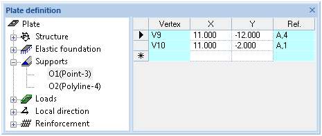
Table of coordinates is supporting clipboard copy/paste functionality.