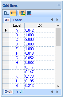
Generating of plate pattern lines is defined by "Grid lines" ![]() :
:
Pattern lines are generated only for plate (cross section) and hole (gap) physical objects. Pattern lines are not generated for the plate geometry design objects dedicated for elastic foundation(s), boundary condition(s), and loading
Pattern lines are generated respectively right lower corner of the plate in the global X and Y directions.
- Construction lines refer to the plate structure, but not to the applied objects. Changing the construction lines will affect plate structure, but will not affect applied objects. This could create invalid situations.
Valid plate |
Invalid plate, while applied objects are outside the plate while plate geometry was changed by editing of construction lines |
- Do not create design objects too close to each other, it is recommended to combine them:
Mesh case loading zone is touching on supporting line. 908 finite elements are generated |
Mesh case loading zone has gap with the supporting line for 3 cm. 6823 finite elements are generated. No sufficient influence in to results but useless increasing time of analysis calculation |