
Rz-Uz diagram for NL supports
An advanced non-linear (NL) analysis can be performed when the degrees of freedom are defined using an Rz–Uz diagram (R - force [kN], U - displacement [m]):
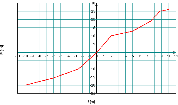
This option is available only if the degree of freedom along the Z-axis is defined as a spring.
Requirements for Rz-Uz diagram input
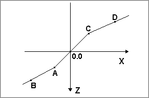
1. The diagram must be continuous; no discontinuity points are allowed.
2. The diagram cannot be defined in the II and IV quadrants.
3. The diagram in the first quadrant (X,0,-Z) represents a compression-only support.
4. The diagram in the third quadrant (X,0,Z) represents a tension-only support.
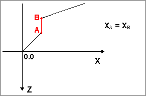
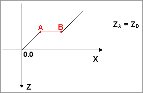
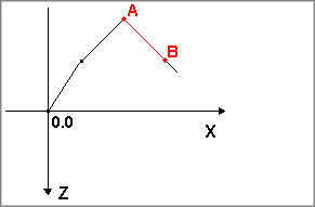
5. The diagram must be strictly increasing, without any vertical (dX=0) or horizontal (dZ=0) segments:
- Vertical branch (dX=0) is not allowed:
- Horizontal branch (dZ=0) is not allowed:
- No portion of the diagram may decrease; the diagram must always increase:
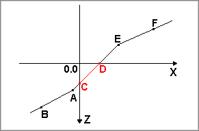
6. The zero point [0;0] is mandatory.
- Diagram without a zero point cannot be defined:
7. Separate diagrams can be defined for the ULS and SLS loading situations.
8. Diagrams for ULS and SLS can be generated using the MatrixTools® Geotechnics compression pile component and imported into MatrixFrame® by pressing the “Get diagram values from Geo” button.