To better understand how to use our plugin, please download the example file: Download
Workflow
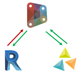
In this example we model a three-hinged frame in Dynamo. We then send the same frame to Revit and MatrixFrame. Changes made in Revit cannot be sent back to Dynamo. From MatrixFrame, at the time of writing, we can view the analysis results back in Dynamo. The geometry forms the basis for the input in Revit and MatrixFrame. That is why only the geometry is set up in Dynamo, and it forms the basis of the model.
Geometry
The three-hinged frame we are going to create consists of 5 elements:
- Two columns
- Two rafters
- A tie rod at the bottom
We want to create a parametric design, which is why we use Dynamo. To make it parametric, we make the column height, the ridge height and the distance between the columns variable.
Nodes
In this example we distinguish between three groups of nodes: nodes for Dynamo, Revit and MatrixFrame. You can find all three groups in the library. The Revit nodes are already in the Dynamo library by default when you use Dynamo for Revit. You have to add the MatrixFrame nodes to your Dynamo library yourself. For help adding the MatrixFrame package, see the installation page on the Matrix-Software website.
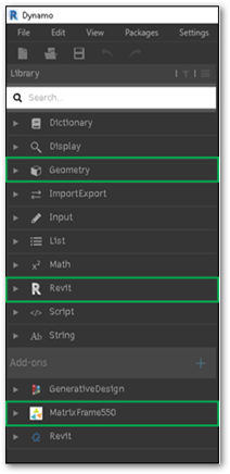
The nodes we will use in Dynamo to create the geometry are:
- Number Sliders
- Point.ByCoordinates
- Line.ByStartPointEndPoint
- List Create
- Code Block
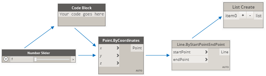
The Point.ByCoordinates and Line.ByStartPointEndPoint nodes are essential to create the geometry. We use the Number Slider nodes to make the geometry parametric. We use the List Create and Code Block nodes to keep the model compact and easy to follow.
For quick access to a node, right-click in the workspace and type the node's name. This is faster than looking it up in the library manually.
Number Slider
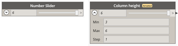
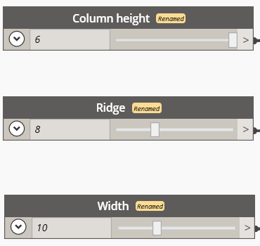
To make the model parametric, we use the Number Slider. With this node we can use a slider to adjust the height of the columns, the height of the ridge and the distance between the columns. As an example, we use the Number Slider for the column height. When you click the drop-down menu, you see Min, Max and Step. Enter the minimum height in Min, the maximum height in Max, and the increment in Step. The display box next to the drop-down menu shows the current value. Double-click the node's title bar to rename the node. The Number Slider node takes no input, so you cannot connect a wire to it. Its output, however, can be connected to several nodes, so several wires can run from this node to other nodes. You will see this later in this example. Now add the Number Sliders for the ridge and the width yourself.
Point.ByCoordinates
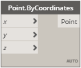
The Point.ByCoordinates nodes represent the points that are later connected by lines. A three-hinged frame with a tie rod at the bottom has five points in total: two at the bottom of the columns, two at the top of the columns and one at the ridge. One important thing to know about the Point.ByCoordinates node: if no input is defined, the node automatically sets all values to 0. The node below therefore has the value 0 for x, y and z, so it can be regarded as an origin node.
The input for the node can be a Number, a Number Slider or a Code Block. If you use a Code Block for the input, make sure the value is treated as a number and not as text. You can recognize a number by its blue color. The image below shows the three input options discussed. Note that each of the x, y and z coordinates accepts only one input.
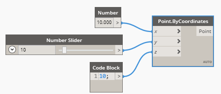
The output of Point.ByCoordinates can be used in several ways. The most common one, and the one we explain in this example, is Line.ByStartPointEndPoint. In some cases it can also be useful to add all coordinates to a list. A point can of course be the start point of one line and the end point of another. That is why a point can have several outputs.
Line.ByStartPointEndPoint
The coordinates discussed in the previous section form points. The points have to be connected to each other to create lines. These lines are needed later as input for Member.CreateByLine, a MatrixFrame node that converts lines into members. This is explained in the section Member.CreateByLine.
In this example we have created five points that we want to connect with lines. For this we use the Line.ByStartPointEndPoint node. This node has two inputs:
- Startpoint
- Endpoint
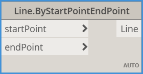
This means that the Point.ByCoordinates nodes created in the previous section form the input for this node. As discussed before, a Point.ByCoordinates node can be the start point of one line and the end point of the next. The simplest example is one line connecting two points. Note that only the x coordinate of point two differs from that of point one.
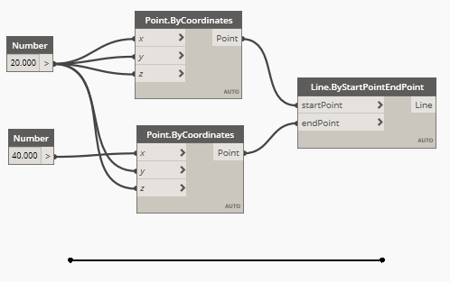
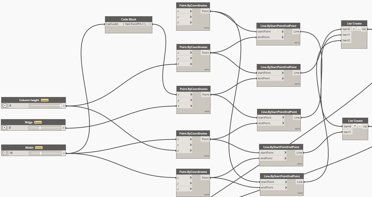
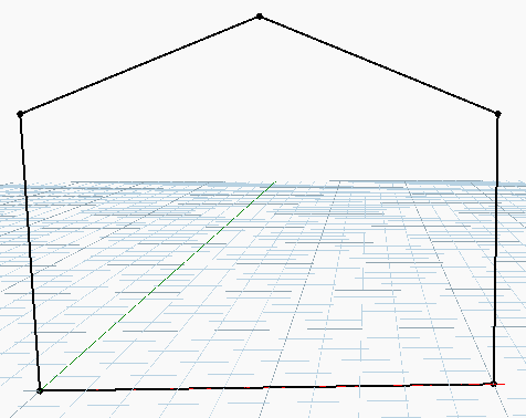
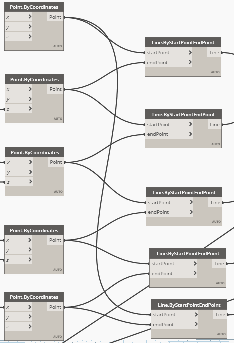
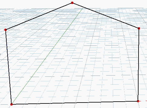
The example we are working out has five points and five lines in total. If you have followed all the steps correctly, you should now see the following geometry in Dynamo, matching the nodes below.
List Create
The List Create node is used to sort separate items or to combine them into one node. List Create can be used for many different purposes, but in our example we use it to distinguish between lines that become beams and lines that become columns.
So we take the set of five lines and make one list of the vertical lines and one list of the horizontal lines. We will use these two lists later to define columns and beams in Revit and assign profiles to them. The same applies to MatrixFrame.
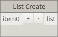
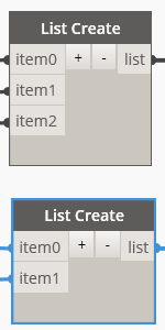
As discussed earlier, our geometry consists of five lines: three beams and two columns. Click the + in the List Create node to add extra input rows. In our example we end up with one List Create node with two items and one List Create node with three items.
Code Block
The only part still missing, deliberately saved for the end, is the Code Block. The Code Block is best described as a text-scripting interface within a visual scripting environment. It is mainly used by advanced users, but there are also cases where a beginner can use it. Worth knowing is the Code Block shortcut: double-click in the workspace and a Code Block appears.
In this section we give two examples of how you can use a Code Block.
The first is a general example. The second shows how we used a Code Block in our model to place the ridge halfway between the columns.
A point using a Code Block
Suppose we have a point with the coordinates x=10, y=-10 and z=10. As discussed earlier, we can choose to create the point the visual way.
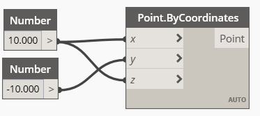
We can go a step further by replacing the two Number nodes with a Code Block that contains the numbers 10 and -10.
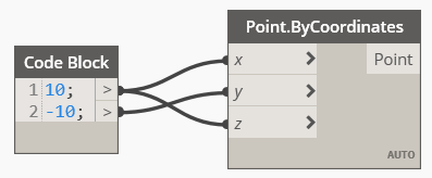
We could go one step further still by putting both the Number nodes and the Point.ByCoordinates node in the Code Block. To do so, we first ask ourselves which nodes we use in the visual approach to create the point: the Number and Point.ByCoordinates nodes. If we put all of this in one Code Block, we should get the same point, x=10, y=-10, z=10. We now place Point.ByCoordinates in the Code Block as well, enter the coordinates between parentheses, separated by commas, and close with a “;”. This marks the end of the line. We could now press Enter and start a new line, for example to add another point.
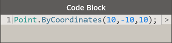
As you can see, models in Dynamo become much more compact when you use a Code Block wherever possible.
Using a Code Block for the ridge
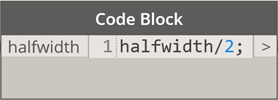
Our example also uses a Code Block, because we want to apply the rule that the ridge is always halfway between the columns. Type “halfwidth/2” in the Code Block and close it. The input for the Code Block is the Number Slider we created to set the distance between the columns. The output of this Code Block is the coordinate of the ridge.
Geometry summary
If you have followed all the steps correctly, your model should consist of the following parts:
- Number slider
- Point.ByCoordinates
- Line.ByStartPointEndpoint
- List Create
- Code Block
The images below show how the nodes should be connected and the resulting visualization.