Rigid links
Rigid links are connections between structural members that do not permit relative motion between them. Rigid links, such as axis offsets or structural imperfections, can be defined as follows.
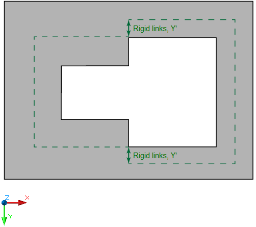
Rigid links can be defined in the local X′ and Z′ directions for 2D-Frame, in the local X′ and Y′ directions for 2D-Grillage, and in the local X′, Y′, and Z′ directions for 3D-Frame projects. The length of a rigid link in the local X′ direction is defined from the member's start or end point toward the centreline. Rigid link lengths in the local Y′ or Z′ direction can be either positive or negative, depending on the direction of the rigid link.
The distance in the local X' direction is an absolute value for both the member start and end and always results in a reduction of the flexible (elastic) part of the member.
The distance in the local Y′ or Z′ direction is defined with respect to the corresponding local Y′ or Z′ axis of the member.
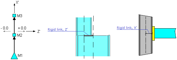
Rigid link position
The position of rigid links with respect to the release is defined as follows:
Loading on rigid links
Any type of external loading (including uniformly distributed, distributed, triangular distributed, self-weight, concentrated loads, etc.), as well as actions such as temperature loading and pre-stressing, can only be applied to the flexible (elastic) part of the member. Loads applied to a rigid link shall be manually transformed into equivalent nodal loads.
| The highlighted load segment cannot be applied directly to the rigid link; it must be converted to nodal forces:

|
| Loading on flexible part of the member | Loading on flexible part of the member and rigid link |
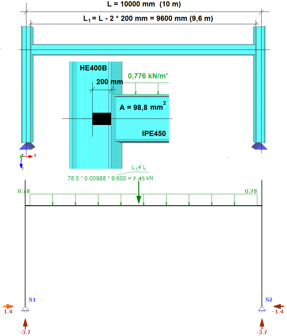
By using rigid links, any structural object - such as an external load, support, or cross-section discontinuity - is referenced to the start or end of the member's flexible (elastic) segment, which differs from the total geometric length (node-to-node) of the member due to the rigid offsets
The referencing and interpretation of the self-weight load is illustrated in the following example:
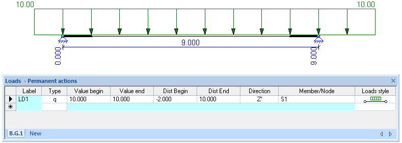
By default, loads are applied to the flexible segment of the member within the range 0 to L, where L represents its length. However, distributed loads can be extended over rigid links or beyond the flexible segment by using negative (-) values for the start offset or distances exceeding L for the end offset:
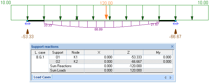
During the calculation, any load segment placed on rigid links and/or outside the member is also taken into account:
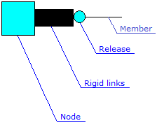
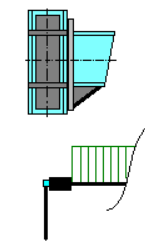
Structural member connections can be represented graphically:
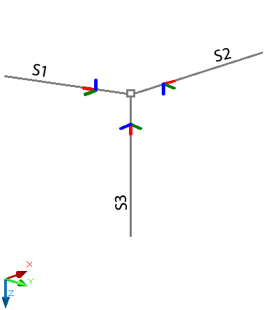
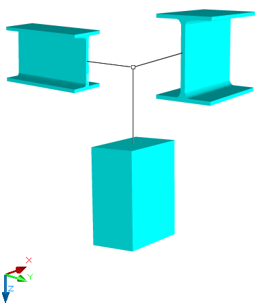
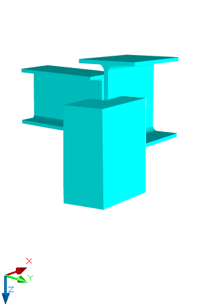
Standard connection constraints are typically not used in practical design when structural axes are shifted. To ensure accurate modeling, rigid links should be applied. A rigid link is a rigid bar element that replaces the idealized geometric connection when axial offsets occur during the design process.
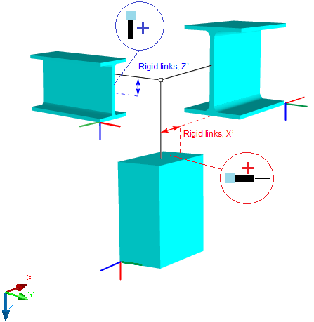
Rigid links in local directions
Rigid links defined in the local directions within a 3D space are illustrated below: