Cross-section properties
The cross-section definition available in MatrixFrame® consists of:
1. Geometrical properties:
- User-defined – basic cross-section properties such as section area (A), elasticity (E), and moment of inertia (I) are calculated and entered manually.
- Parametric – cross-section properties with the option to enter custom section parameters.
- Database – cross-section properties defined using the manufacturer’s structural shapes database.
2. Material properties – cross-section material type, available only for parametric and database sections.
All geometrical properties are defined and calculated in meters. The input is validated to prevent incorrect values. Once a cross-section is assigned to a structural member, its geometrical and physical properties are displayed in the grid.
Note: the reverse assignment (modifying the cross-section after assignment) is not possible.
Cross-section names
Cross-section names are generated in different ways depending on the type of section:
User-defined – names must be entered manually.
Parametric – names are generated automatically using the short name of the section shape and its dimensions in millimeters.
Database – names are generated automatically from the original manufacturer names.
In all cases, it is possible to modify the section names in the grid.
Parameters of database cross-sections are defined by the manufacturer and cannot be modified directly. However, if a section or material name is changed at your discretion, the section becomes editable, and any modifications to its parameters are saved in the database as a new section or material.
Advanced cross section properties
Several advanced cross section properties are available:
| Property | Definition | Comments |
| Tapered | A tapered cross-section has different height values at the start and end of the member. Only parametric rectangular cross-sections can be tapered in both height and width simultaneously. | |
| BiMaterial | Only parametric rectangular cross-sections can be defined as BiMaterial, consisting of two different materials. | |
| Tension | A structural member defined as tension-only carries load only in tension, e.g., a bracing. If a tension-only member is subjected to compression, it is excluded from the calculations. | By default, both Tension and Compression options are active. If both options are disabled simultaneously, the member is temporarily removed from the calculations. |
| Compression | A structural member defined as compression-only carries load only in compression. If a compression-only member is subjected to tension, it is excluded from the calculations. | |
| Cable | A structural member defined as a cable (only applicable to circular parametric cross-sections) carries load primarily in tension. It can optionally be influenced by pre-stressing, a method used to overcome the natural weakness of the member in tension. | |
| Castellated | Only I- and H-shaped cross-sections can be defined as castellated. Restriction: the height of a castellated cross-section must be less than twice the height of the original cross-section from which it is produced. | The main geometric characteristic values of a castellated cross-section with hexagonal openings depend on the height of the original cross-section , the height of the castellated cross-section , and the geometry and positioning of the hexagonal openings. For the Castellated profile branch in the sections database, the geometric relationships are defined as follows: 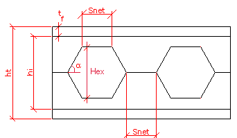
The DB section properties are recalculated using the characteristic geometric values described above, which can be entered freely in the DB. Modifying these values triggers a recalculation of the section properties and can serve as a solid basis for creating new cross-section families. 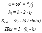 |
| Density, [kN/m³] | Mass per unit volume, used for the calculation of self-weight. | |
| Torsional/Polar moment of inertia (It), [m4] | Moment of inertia used for torsion calculations. | |
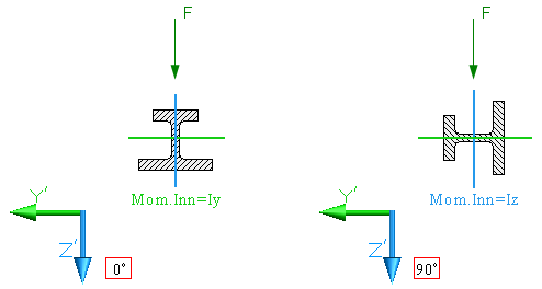
| Second moment of area (Mom. Inn.), [m4] | The second moment of area (also known as the area moment of inertia, planar moment of inertia, or second moment of inertia) is a property of a cross-section used to predict the resistance of beams to bending and deflection around an axis lying in the cross-sectional plane. | 2D-Frame: The moments of inertia depend on the cross-section rotation angle (for 2D-Frame, angles in multiples of 90°), as well as the cross-section shape and dimensions. The rotation angle is formal: the local axes and related properties (moments of inertia, loads, etc.) are not physically rotated. Instead, the moments of inertia switch the values of and according to the cross-section rotation angle:
3D-Frame: The moments of inertia do not change with the cross-section rotation angle about the X′ axis. In 3D-Frame, the local coordinate system is used: when the rotation angle is changed, the cross-section and all related properties (moments of inertia, loads, etc.) rotate together with the Y′ and Z′ axes: 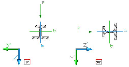 |
| Moment of inertia (Iuv), [m4] | Used for stability analysis (for example, tension-only elements) as the minimum of , , , and :
Iuv=min(Iy,Iz,Iu,Iv)
where: – moments of inertia related to the principal axes and , rotated by angle counterclockwise (CCW) from the vertical. | |
| Poisson's ratio (ν) | The ratio of transverse strain (perpendicular to the applied load) to axial strain (in the direction of the applied load) when a material is stretched (under tensile loading). | Poisson’s ratio is used, for example, in the calculation of torsional rigidity GJ under applied torque and in shear force correction of nodal rotations during structural analysis. where: E - Young's modulus, [kN/m²] ν – Poisson’s ratio |
| Shear area (Avy , Avz), [m²] | Used in the calculation of the form factor for performing shear force correction on nodal rotations during structural analysis (only if shear force correction is enabled in the analysis options). | The form factor v of the cross section is related to the shear area as follows:   where: Av - shear area of the cross section A - total area of the cross section
For a rectangular cross section, the form factor can be calculated as: |
| Prestressing, [kN] | Prestressing is applicable only to cable elements. Prestressing defined as a predefined action on a member affects all load cases and load combinations. Initial prestressing applied to an element indirectly affects the members connected to it; therefore, this action is similar to a temperature-induced elongation. | Prestressing applied to prefabricated concrete elements represents a different concept, where the prestressing action is confined to the element itself and is not distributed to the connected members. |
Cross-section distribution
The cross-section definition allows sections to be assigned based on member characteristics. There is a difference in functionality between 2D/3D-Frame projects and 2D-Grillage / 1D-Beam projects in MatrixFrame®:
2D- and 3D-Frame – a single cross-section can be assigned to a member. If a new section is assigned, it updates the existing one.
2D-Grillage and 1D-Beam – multiple user-defined cross-sections can be assigned to a single member.