The tab Deflections is only available when the modules "Concrete link FEM plate" (282), "Concrete deflections FEM" (296) – is part of the license, material concrete is defined and characteristic /frequent and quasi-permanent load combination is present. Also Advanced analysis should be performed with the Assumption "FNL" set on true as well as proper settings in "Analysis Options" for "SLS Analysis method" <NL analysis>.
|
Value |
Description |
|
|
Envelope + / Envelope - drop-down items are representing redistribution of deflection envelops respectively positive and negative direction of Z axis |
|
wmax |
Design value of the remaining total deflection in Z (Z’)-direction, with taking in to account pre-camber wmax = (W1+ W2+ W3) - Wc [mm] |
|
(W2 + W3) |
Design value of a variation of the deflections in Z (Z’)-direction due to variable loading + time dependent deformations due to permanent load during the exploitation of the building (W2 + W3) [mm] |
Deflection check according EN, NEN-EN, NBN-EN 1990 is satisfying requirements described by EN, NEN-EN, NBN-EN 1990 # A1.4.3.
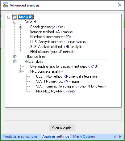
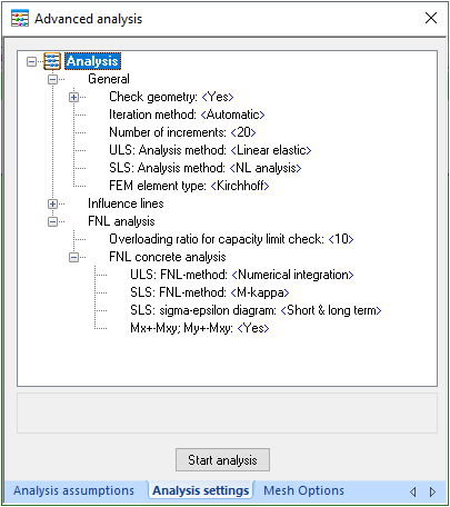
Calculation presumptions presets are defined using Analysis settings as:
Calculating of concrete deflections using "Short & long term" sigma-epsilon diagram option implies definition rare and quasi-permanent combinations are taking in to account influence of creep effects.
These effect on common result values are shown in Results tab by choosing load combinations drop-down items respectively for:
|
Value |
Description |
|
Qu.C.1[Sh.T.] |
Results using Quasi-permanent loading via short term σ-ε diagram |
|
Qu.C.1[L.T.] |
Results using Quasi-permanent loading via long term σ-ε diagram |
|
Qu.C.1[Creep] |
Results using Quasi-permanent loading via taking in to account creep effect as difference between Long and Short term results |
|
Ch.C.[Creep], Fr.C.[Creep] |
Results using Characteristic loading combinations is taking in to account creep effect |
|
Ch.C., Fr.C. |
Results using Characteristic loading combinations is taking in to account the short term variable actions |
All the deflections specific values doing some influence in to deflections wmax (u;add/u;end) or (W2 + W3) calculation for some separate finite element, are shown in the tab Deflections. By choose the variable action described loading combination, for example Ch.C.2 or Fr.C. 2, corresponding wmax (u;add/u;end) or (W2 + W3) chart is represented:
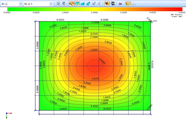
Using the tooltip by pointing an finite element via mouse and pressing right mouse button the components of wmax (u;add/u;end) or (W2 + W3) calculation is represented:
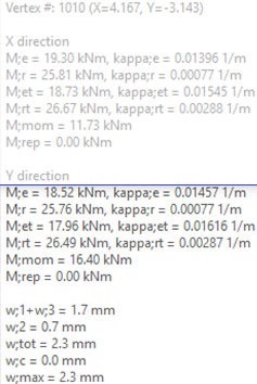
Drop-down selection Qu.C. 1[Sh.T.] is represented wmax (u;add/u;end) or (W2 + W3), where the W3 component is calculated using Qu.C. 1[Sh.T.] loading combination presets.
Deflections calculation process is ruled by non-linear processing which calculation options are described in "Analysis settings" tab as:
Default "Automatic" iteration method in based on minimal quantity of iterations is ensure convergence of the solution by using minimal calculation time.
Changing of iteration method in to the "Linear" by manipulating with the number of increments is possible to make investigation to get some better convergence using more increment steps v.s. calculation time.
Nonlinear calculation of deflections is default (SLS:Analysis method <NL analysis>). By choosing of linear calculation of deflections (SLS:Analysis method <Linear elastic>) would be not possible creep effects satisfying requirements described by EN, NEN-EN, NBN-EN 1990#A1.4.3.
Calculation assumptions:
Deflection check with the applied As;prov=As;req(ULS) is done based on the FNL results, while As;req(ULS) is calculated based on linear analysis results. Because of the force redistribution during FNL analysis, applied As;prov sometimes can not ensure bearing capacity of the plate, as then the destruction of the structure appears. For example, after redistribution of forces, the tension force can appear in the element(s), where As;prov isn't applied at all, because As;prov = As;req is applied based on LE analysis. So, such an element is completely destroyed (may be on 0.1 of the total loading) and the calculation is stopped.