
Tension elimination
Tension in the elastic foundation, which results in shear forces, is eliminated through an iterative process. The elastic foundation incorporating tension elimination is globally defined, i.e., it acts in the direction of the global coordinate system. The commonly used elastic foundation is locally defined for each member, whereas the tension-elimination version is always globally defined:
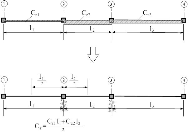
Tension elimination by nodal spring value
Tension elimination using the nodal spring value for a very small element is performed by employing a single-node, globally oriented FE with axial stiffness only (no length, no support, and no second node).
Members with an inclination angle α (excluding α = ±90° and α = ±270°) use Z-direction springs, whereas for vertical members with α = ±90° or α = ±270°, the elastic foundation is substituted with X-direction springs.
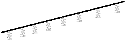 |  |
Z-spring: applicable for any angle α (excluding α = ±90° and α = ±270°) | X-spring: applicable for α = ±90° or α = ±270° |
Placement of elastic foundation for vertical members
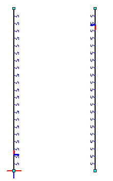
The placement of the elastic foundation for vertical members (e.g., walls) depends on the local member orientation. For members oriented bottom-to-top, the foundation is applied to the right side of the wall. Conversely, for members oriented top-to-bottom, it is applied to the left side. This convention specifically influences the behavior of elastic foundations with tension elimination.
Local orientation of the elastic foundation with tension elimination for vertical members (walls):
Use cases
1. Calculation without tension elimination
This is the standard case where both compression and tension zones of the elastic foundation are active (tension could be eliminated). In zones where the beam displacement is top-oriented and bending moments act on the top side of the beam, the elastic foundation experiences tension, which is not reliable for real-life modeling.
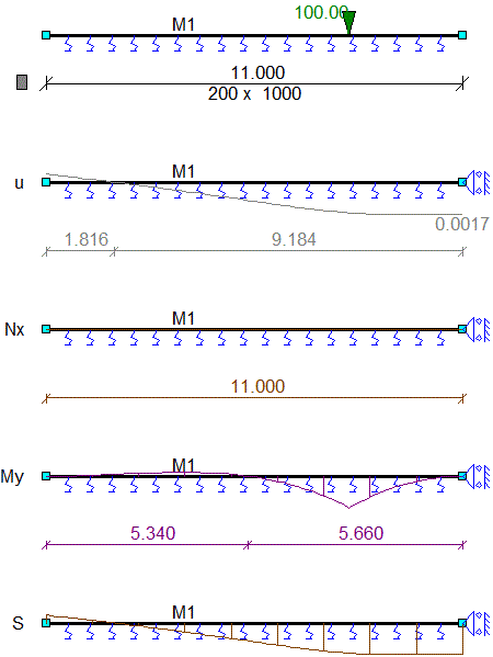
2. Calculation with tension elimination
In this case, only the compression zones of the elastic foundation are active, while tension zones are eliminated during the non-linear (NL) calculation process.
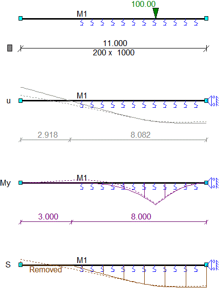
3. Calculation with only compression acting on the elastic foundation
Tension zones of the elastic foundation are eliminated during the non-linear (NL) calculation process. As a result, no subgrade support remains beneath the structure. The structure therefore exhibits excessive displacements. Consequently, results are not reliable for design purposes.
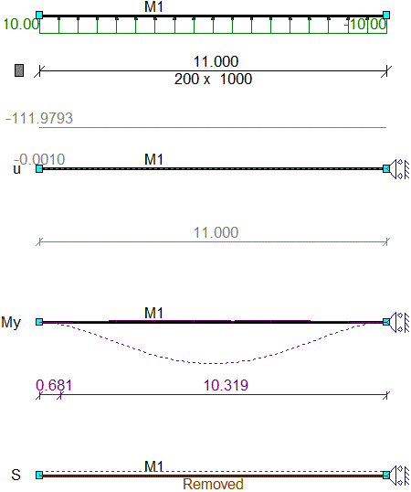
4. Calculation with only tension acting on the elastic foundation
Compression zones of the elastic foundation are eliminated during the non-linear (NL) calculation process. As a result, no subgrade support remains beneath the structure. The structure therefore exhibits excessive displacements. Consequently, results such as bending moments are not reliable for design purposes.
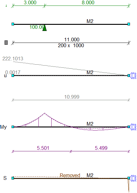
5. Analysis of a tunnel using elastic foundation on vertical walls
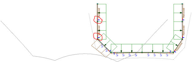 | 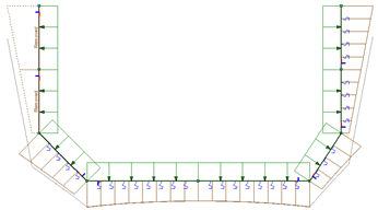 |
| Incorrect modeling of vertical walls | Correct modeling of vertical walls |