Objects can be linked to:
the element/member length proportion, denoted as “H” (half of the member length), “Q” (quarter of the member length), and “3Q” (three quarters of the member length)
Use cases:
P2(H) – section property P2 is linked to the half of the member length position;
E1(Q) – Elastic foundation property E1 is linked to the quarter of the member length position;
Support O1 is placed at a distance of three quarters of the length of member S11:

Load LD11 is linked to the half of the member length of member S11:

the intersection of elements/members (“member_label#:member_label#”)
Use cases:
P1(S2:S6) – section property P1 is linked to the intersection of members S2 and S6;
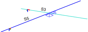
Support O5 is placed on member S3 and linked to the intersection of members S3 and S5:

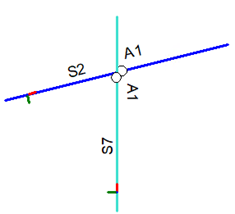
Release A1 is placed on member S2 at the intersection of members S2 and S7 (designated as S2:S7), directed towards the end of member S2;
Another release A1 is placed on member S7 at the same intersection (S2:S7), directed towards the start of member S7: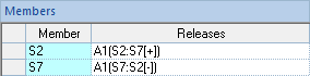
Notes:
the notation “[-]” and “[+]” is valid exclusively for defining releases;
different placement of releases on a rigid connectivity joint can result in a different force redistribution, for example:

* the rigid segment is highlighted in grey
referencing intersecting members using the #:# notation (e.g. S3:S17) eliminates coordinate input inaccuracies (for example, such as entering 3.227).
another object, denoted as “object_label#”
Use cases:
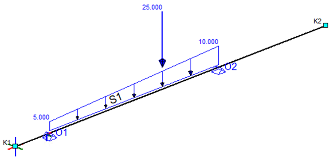
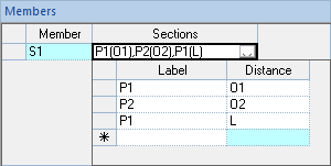
Section property P1 is applied to member S1 from the start of the member to support O1. Section property P2 is applied to member S1 from support O1 to support O2. Finally, section property P1 continues from support O2 to the end of the member:

Load LD1 is applied to member S1, with its start position linked to support O1 and its end position linked to support O2. Load LD2 is applied to member S1 and linked to the coordinate of support O2 decreased by 2.0 meters: