In the stability part of Steel, Concrete and Timber, the buckling length for each member is calculated based on results M and φ in the special combination group "Buckling Combination". In case multiple combinations are defined, the max. buckling length is taken as decisive.
As stated before, loads should be applied in a way that the buckling affine deflections are simulated. The proper way is to apply the acting axial force in a member as horizontal load at the member. In case the axial force is more or less equal in the member, this simply could be simulated by a horizontal load qG equal to the self weight of the member.
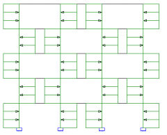
Keep in mind that multiple Eigen-shapes are possible for the buckling curvature. Actually it means that at least 2 curvatures should be taken into account:
- Asymmetric: especially in case of sway frames
- Symmetric: especially in case of braced frames
 |
 |
 |
 |