M-Phi diagram for steel joint connections
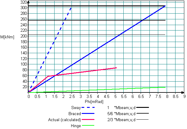
It is possible to perform a not linear (NL) analysis for steel joint connections in case the degrees of freedom are defined by using a M-Phi diagram (M - moment [kNm], Phi - angle of rotation [mRad]). For the M-Phi diagram angular rotation Phi has a global meaning.
The M-Phi diagram in absolute units:
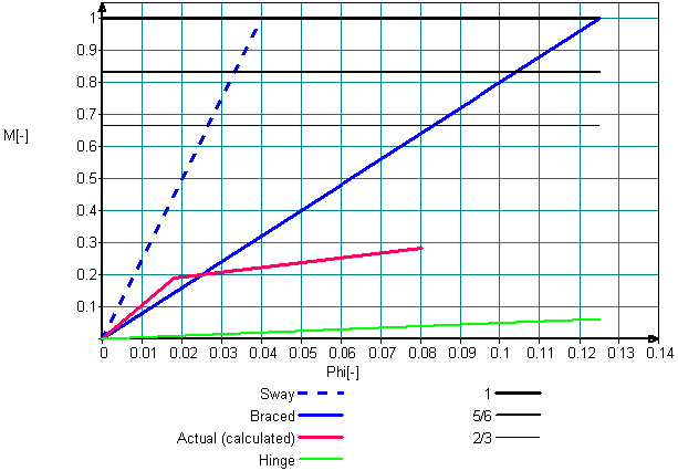
The M-Phi diagram in relative units:
Requirements for M-Phi diagram input
1. diagram may not have discontinuity points (according to continuous function definition)
2. diagram may not be defined in II and IV quadrants
3. diagram must be increasing without vertical (dX=0) or horizontal (dZ=0) branches
- Vertical branch (dX=0) not allowed:
- Horizontal branch (dZ=0) not allowed:
- The diagram must be only increasing: any part of the diagram can't be directed down as:
4. zero point [0;0] is absolutely necessary:
- The diagram without zero point can not be defined:
After calculation is performed and the M-Phi diagram of joint connections is created, MatrixFrame® provides a feedback to not linear (NL) releases to recalculate the updated not linear spring releases.