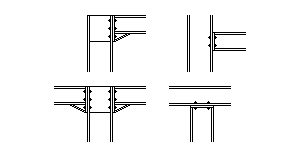
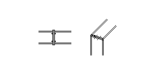
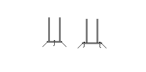
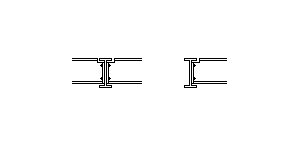
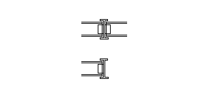
Joint connections types:
|
Parameter |
Description |
||||||
|
Node |
Structure nodes marked with the numbered symbol K |
||||||
|
Bottom, Top, Left, Right |
Position of structural elements in relation to the connection point; the position is marked with the numbered symbol S and the defined section code |
||||||
|
Topology |
All joint connections could be described as connection from 2 members or as member connected with a support. For more information see the Joint Connection Topology table below |
||||||
|
Connection Type |
|
||||||
|
Label |
Connection label marked with the numbered symbol C |
||||||
|
MatrixTools® |
Data export to MatrixTools® |
||||||
|
UC Max. |
Maximal Unity Check calculation value |
Joint connections topology:
|
Abbreviation |
Attributive sign |
Topology value |
Axes |
|
|
B-B |
|
|
Beam-Beam |
X-X, Y-Y |
|
MB-CB |
|
|
MotherBeam-ChildBeam |
X0Y |
|
C-B |
|
|
Column-Beam |
Z0X, Z0Y |
|
C-C |
|
|
Column-Column |
Z-Z |
|
C-S |
|
|
Column-Support |
Z |
The connection B-B and C-C are in theoretical way the same, only visualization and practical purpose is different. The connection C-B and MB-CB also are in theoretical way the same, only visualization and practical purpose is different.
As logical result of the topology configuration described in the previous chapter, the nodal connection could be described as a configuration of specific member end connections (local connection types) assembling. Basic local connection:
|
Abbreviation |
Attributive sign |
Type value |
|
S |
|
Support |
|
X |
|
Continuous |
|
W |
|
Welding |
|
EP |
|
End plate |
|
WP |
|
Web plate |
|
FP |
|
Flange plate |
