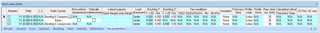
Steel check represents fire protection analysis results: gives information about element, initial conditions, internal forces and fire protection analysis results according EN 1993-1-2 and related national application documents.
| Member |
Description of the member with defined conditions for the fire protection calculation. Member label. The column shall be filled-in automatically during graphic prescribing of the fire protection to the structure in the Structure View window. |
| L.C. |
All results are shown from indicated load combination. Label of the load combination. The column shall be filled-in automatically during graphic prescribing of the fire protection to the structure in the Structure View window. |
| Static System |
Sets the member condition for the Fire Protection analysis.
Used for fire protection analysis as primary input data. Description of the element, can be calculated corresponding the rules described in EN 1993-1-2#6.2.3 for the element under tension, EN 1993-1-2#6.2.3 for the element under compression (Column), EN 1993-1-2#6.2.5 for the bending element (Beam), EN 1993-1-2#6.2.5 for the bending and axial force (compression) acting over an element and for Other elements. For the Other elements required heat resistance calculation will be performed depend on the custom value of the degree of utilization.
Description of the Member scheme. NEN 6072 distinguishes the next statically determined schemes:
This application supports all but the bars under tension. The bars under tension however can be treated also as all side heated statically determined beam. The eccentrically compressed member shall be analyzed as a centrally compressed member with use of an equivalent axial force. See also: “Overspannend Staal", Construeren A, paragraaf 5.5. |
| Fire conditions, Neq;s;d |
Acting internal element axial force for the fire protection analysis. Axial force in the normal conditions, when environment temperature is 20°C. |
| Buckling on T=20°C |
Buckling length of the member for the Fire Protection analysis. Buckling length of the member in normal conditions, when environment temperature is 20°C. The equivalent axial force for eccentrically loaded columns shall be calculated according art. 9.2.2 van NEN 6072 using the buckling factor buc; 20 C without use of reduced (fire) buckling length. See “Overspannend Staal", Construeren A, par. 5.5. |
| Buckling on T=(fire) |
Buckling length of the member for the Fire Protection analysis. Used for fire protection analysis as primary input data. Buckling length on T=(fire) - buckling length of the element (l;fi) for the fire design situation according EN 1993-1-2#4.2.3.2(3 and 5), where buckling length on T=20°C is describing buckling length of the element (l) for the normal situation. For braced frames this may be determined with use of the upper and lower restraints. If however the fire is restricted to a single floor or compartment, then the buckling length can be taken as ( See NEN 6072 art. 10.3.2.1):
The calculation of the buckling factor shall be done using the instability curve c (See NEN 6770, art. 12.1.1.4) |
| Fire conditions, Neq;s;d |
Acting internal element axial force for the fire protection analysis. Axial force in the normal conditions, when environment temperature is 20°C. |
| Fire conditions, Neq;s;d |
Internal Member Forces for the Fire Protection Analysis. The value shown for Neq;s;d is the so-called "equivalent" axial forces which takes into account effects of misalignment or excentricities, according NEN6072 art 9.2.2 , see also book “Overspannend Staal", Construeren A, par 5.5. |
| Fire conditions, Nx;s;d |
Internal member forces for the Fire Protection Analysis. Axial force in the normal conditions, when environment Temperature is 20°C. |
| Fire conditions, Mequiv |
Internal member forces for the Fire Protection Analysis. The equivalent acting bending moment Mequiv, under fire conditions is determined according NEN6770, art. 12.3.1.2.1 van NEN 6770. In general this value is lower than the moment as a results of eccentricity at the connection column-beam. |
| Fire conditions, Mysd |
Internal member forces for the Fire Protection Analysis. The acting design bending, Mysd should be taken less or equal to Myud, the design bending capacity. The acting bending Moment Mysd under fire conditions may be determined using plasticity. |
| M;eq;theta;s |
The equivalent acting bending moment, under fire conditions. In general this value is lower than the moment as a results of eccentricity at the connection column-beam. |
| Mu (µ0) |
Used for fire protection analysis. Pre-calculated or primary input data. Degree of utilization µ0 according EN 1993-1-2#4.2.4. |
| fy on T=(fire) |
Used for fire protection analysis. Pre-calculated. Steel strength fy in the fire situation according EN 1993-1-2#(Table 3.1.). |
| Fire conditions, h |
Used for the critical temperature calculation. Coefficient, which depends on the exploitation of the bearing capacity. |
| Fire conditions, k |
Uses for the critical temperature calculation. Coefficient, which depends on the type of the member (beam or column and etc.) and on the heating surface. |
| Chi (χ) |
Buckling factor in the fire situation according EN 1993-1-2#4.2.3.2. |
| Insulation |
Used for the fire protection analysis. Type of insulation material. |
| Thickness |
Used for the fire protection analysis. The thickness of the applied insulation material. Could be entered in mm. However, since verified data is only available for a limited amount of thicknesses, user is restricted to the upper and lower boundary of this value. A direct result of this is that, in case of a critical temperature higher than the value for which verified test results are available, this calculated critical temperature shall be set back to the one for which we do have test results. |
| Profile code |
Uses for the fire protection analysis. Description of the heating surface. |
| Profile factor |
Used for the fire protection analysis. The so-called “profile factor” has been defined as the ratio between the exposed heat surface of the considered section and the volume which absorbs the heat. In this software is chosen for a 2 dimensional approach, so the Unit of this “profile code” shall be: [m/m2]. This factor is decisive for the speed of temperature increase and is determined by the geometry of the section and the part of the section, which is exposed to fire. (see NEN6072 fig. 3 and book "Overspannend Staal", Construeren A, Chapter 5.). For sections chosen from database the program calculates the profile factor. However, one can always overwrite this factor by editing. |
| Required heat resistance |
Used for the fire protection analysis. The required heat resistance must be entered in minutes. On base of this, the critical temperature shall be calculated as well as the time after which this temperature has been reached.The UC of this reflects the resistance against fire. |
| Calculated critical time |
Represents fire protection analysis results. The max period of time when Member could keep the added loads in fire conditions. |
| Calculated critical temperature |
Represents fire protection analysis results. Max temperature accessible for section. |
| t;Theta;a |
Represents fire protection analysis results. Necessary time to reach critical steel temperature. In fact it is max period of time when element could keep the added loads in fire conditions. |
| Theta;a;spec;max |
Represents fire protection analysis results. Maximal steel temperature corresponding to required fire resistance. |
| Theta;g;t;max |
Represents fire protection analysis results. Ambient gas temperature corresponding to required fire resistance. |
| Theta;a;cr |
Represents fire protection analysis results. Critical steel temperature in fire situation. |
| UC Fire |
Represents fire protection analysis results. Unity Check for fire situation. Unity Check for fire situation representing ratio: Required time / t;Theta;a. |
| UC Max |
Represents analysis results. Max Unity Check from all performed checks. |