Positioning of the punching reinforcement by default is defined according to the central column "Y" and "Z" axis separately, respectively, to the radial ("Sr"-the radial distance between reinforcement perimeters) and tangential ("St"- the tangential distance between bars) directions (Fig 1) of the reinforcement perimeter lines:
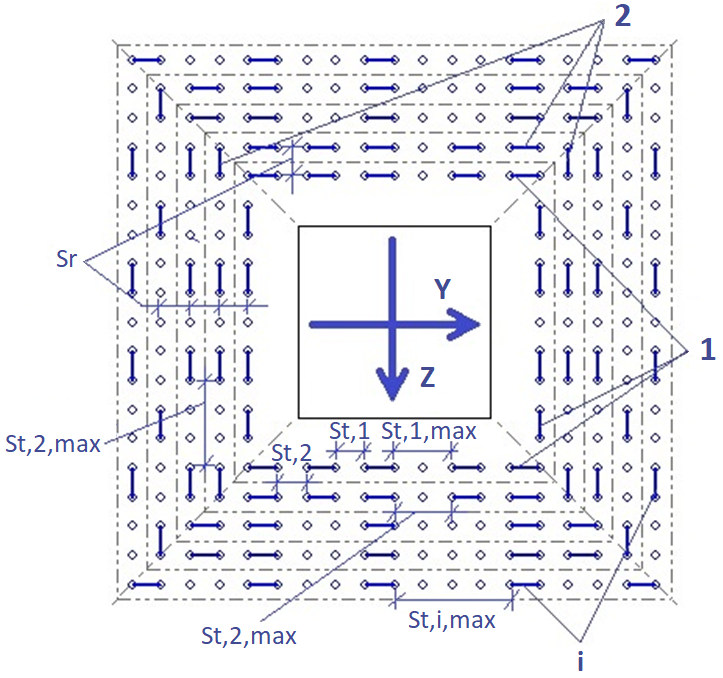
Fig 1. Distances "Sr" and "St" on the column axis lines for double axis symmetrical reinforcement situation (internal column)
Reinforcement pattern could be defined for the internal (Fig 2a), edge (Fig 2b) or corner (Fig 2d) located column with the possibility to do shift of the central column axis to the column edge (Fig 2c):

Fig 2. Column location for the punching situation
The shift mentioned in Fig 2c could be handled by manual input of the "Distance to the column-edge" that should be performed twice for the situation where the column is placed on the edge corner (Fig 2d). The result part representing reinforcement represents the final applied pattern situation "corner or edge + shift". For the Fig 2b "Edge" column location, the 1st perimeter punching reinforcement perpendicular to the "Y" direction is 4R6, while the 1st perimeter punching reinforcement perpendicular to the "Z" direction is 2R6. For the Fig 2c "Edge+Shift" column location, the 1st perimeter punching reinforcement perpendicular to the "Y" direction remains 4R6, while the 1st perimeter punching reinforcement perpendicular to the "Z" direction while the Y shift becomes 3R6 value.
The reinforcement pattern itself could be applied using radial "Yr" or "Zr" (Fig 3a), dual axis "YZ" or "ZY" (Fig 3b), or single axis "Y", "Z" (Fig 3c), pattern rules applied on Y and Z axis uniformly:
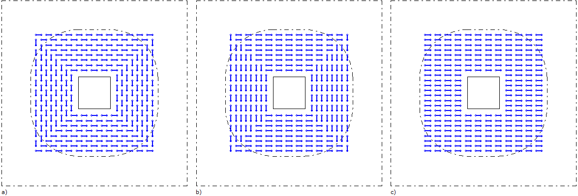
Fig 3. Punching reinforcement pattern
Uniformly applied radial "Yr" or "Zr" (Fig 3a) or dual axis "YZ" or "ZY" (Fig 3b) pattern could be redefined to the mixed mode tangential-radial or tangential-dual axis mode, by using Results grid Stirrups direction drop-down (Fig 4):
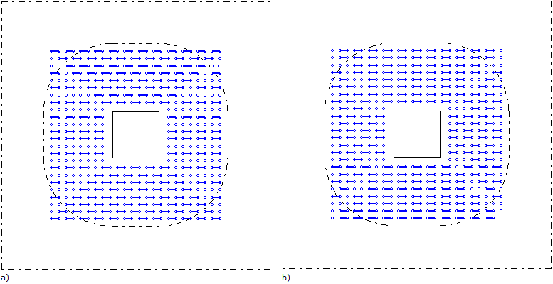
Fig 4. Mixed mode punching reinforcement pattern for radial and dual axis situations
Performing the punching reinforcement reduction using "Reduction" flag, used reinforcement could be reduced by leaving on the reinforcement perimeters the first perimeter reinforcement count (Fig 5):
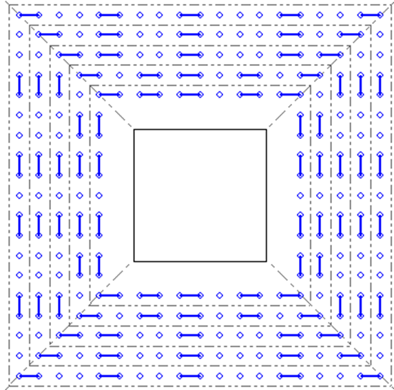
Fig 5. Reduced punching reinforcement situation for the radial pattern
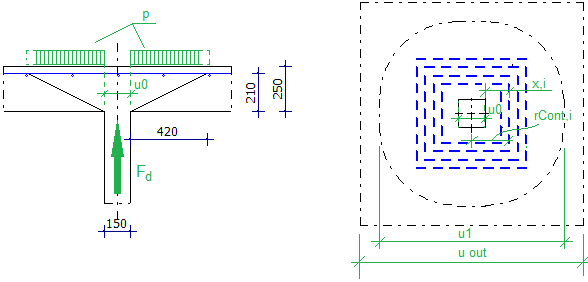
Fig 6. Positioning of loading area
Selection of applied pattern, mixed mode so far reduction of reinforcement is possible for the Punching calculation advanced punching only (Technical module No. 387).
The shear force VEd is calculating as VEd = Fd – A*p (Fig 6), where area A (Fig 5) is calculated exclusive the loaded area u0 for all perimeters. VEd is editable in advanced punching module.
The detailing rules and limitations of link legs are described in the EN1992-1-1#9.4.3 (1):
- Stirrups legs should have at least 2 perimeters, where bent-up bars could have 1 perimeter;
- Link legs spacing limit check as Sr < Sr,max=0.75d is only related to the stirrups, so in case of bent-up bars there is no check sr < sr,max;
According to the EN1992-1-1#9.4.3 (Fig 9.10b) bent-up bar should be checked for the spacing of link legs around a perimeter should not exceed 2d. So, an exact check is not possible. Also, according to the EN1992-1-1#9.4.3 (4) only rules for a check at the top side are required (and performed).
The required reinforcement contours count indicated by "Next" mark should satisfy the limit condition for the i-th contour as x;i < (u;out – kd). Not satisfactory condition indicated by "Stop" mark is pointing to the not required (redundant) punching reinforcement contour.
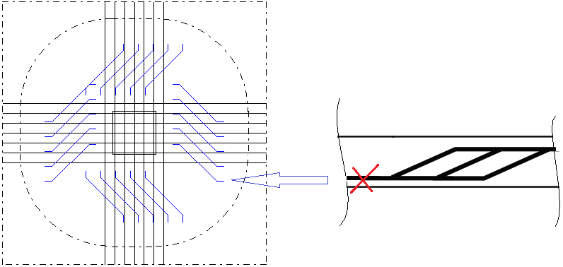
There are no requirements for the length of the horizontal branches from the bent-up bars not shown in the illustration:
