The "Member design" dialog applies to both steel and timber members. This feature provides tools to optimize and design cross-sections based on user-defined groups and specific design criteria, such as utilization targets, deflections, and fire resistance.
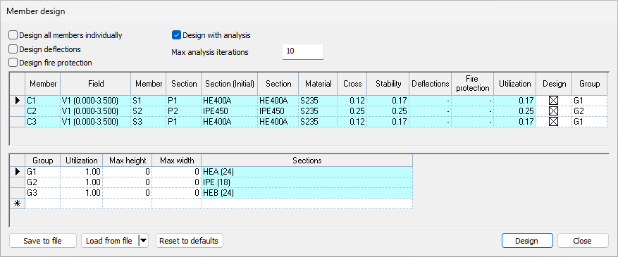
Settings
Design all members individually
Turned off: All members assigned to the same group (with design enabled) share a single section with the same ID. The design optimization is based on the maximum Unity Check (UC) value among all members sharing that ID.
Turned on: Before the design process begins, every individual member is assigned a duplicated section. The design optimization runs using only the utilization of that specific member. As a result, after the design process, each member may receive a different section to precisely satisfy its utilization condition.
Design deflections
- Turned off: Deflection checks are ignored during the design process.
- Turned on: Deflection checks are taken into account for the design.
Note: Deflection optimization is not applied to columns. For columns, the deflection cell displays a dash '–' accompanied by an explanatory tooltip.
Design fire protection
- Turned off: Fire resistance checks are ignored.
- Turned on: Fire resistance checks are taken into account during the design process.
Design with analysis
Turned off: Member design is performed without recalculating analysis results after a section changes.
Note: Utilization values will not be fully accurate in this mode, as changing section properties naturally alters the analysis results.
Turned on: The design process includes recalculation of analysis results. The process continues until either the maximum number of iterations is reached or the target utilization values are satisfied.
"Members" grid

The "Members" grid lists all the structural elements available for design.
Section (initial): Always displays the original cross-sections that were applied to the members before opening the dialog.
Section: Initially displays the same cross-section as the initial state. After the design process is run, it displays the newly selected/optimized section.
Design: Checked members are included in the design process; unchecked members are skipped.
Group: Displays the assigned design group. The section list options and target utilization values are taken directly from this group. If an invalid group is assigned, the cell displays "N/A" and the member will be ignored during design.
"Groups" grid

An unlimited number of section groups can be created and managed in this grid for member design.
Each group is defined by a Utilization target and a specific section list.
Quick filters are available to limit the allowed sections by height or width.
All sections currently available for a group are displayed in a tooltip.
Clicking the ellipsis button "..." inside the "Sections" cell opens a sub-dialog to manually select specific sections to be used for that group.
Data management
Saving settings & groups
Automatic save: Closing the "Member design" dialog automatically saves all current settings and section groups. The next time the dialog is opened, the last used values load automatically.
File export/import: The "Save to file" button allows saving the current data manually. This saved data can be restored at any time using the "Load from file" button.
Reset to defaults
Clicking this option performs the following automated procedures:
Deletes all custom groups.
Creates a new group for every unique section ID present in the model.
By default, selects all sections from the same series for that group (e.g., if a member's initial section is IPE300, all available IPE profiles will automatically be selected in its group list).