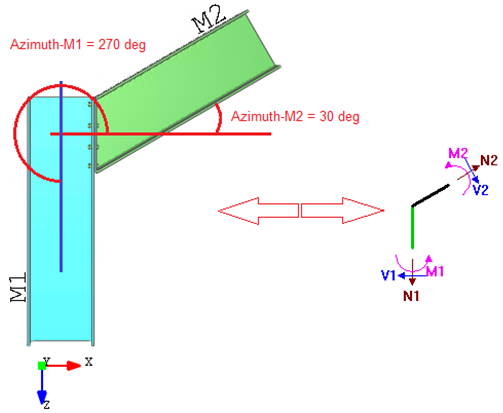
Azimuth-Elevation spatial (3D) positioning of the members:
1. Describing its positioning during the joint connectivity design and has direct relation with the default applied load directions:
2. Is validated against invalid structural design:
2.1. Validation on beam continuity:
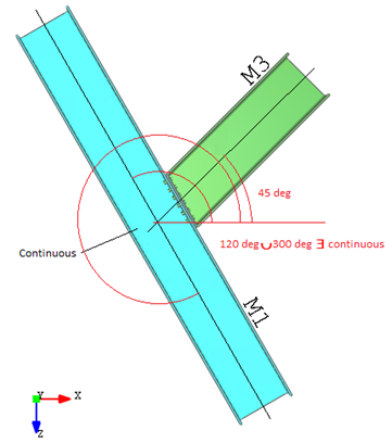
In case of azimuth of beams by angle (120 deg-M2 and 300 deg-M1) will not satisfy the "continuous beam (straight line)" condition, design will be marked as invalid
2.2. Validation against not supported structural design:
 |
 |
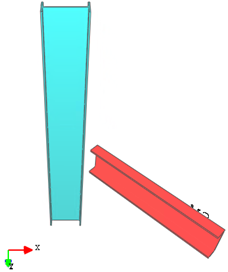 |
|
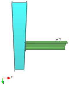
a) Valid situation. Beam to Column connectivity Azimuth = Elevation = 0 deg |
b) Valid situation. Beam to Column connectivity Azimuth = 90 deg, Elevation = 0 deg |
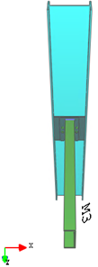
c) Invalid, by design not supported situation. Beam to Column connectivity Azimuth = 45 deg, Elevation = 0 deg |