By means of the criteria a CPT can be defined into a number of segments. Here the basic assumption should be applied: the geotechnical parameters for every segment have a constant value. This segment arrangement shows some similarities with a soil drilling. We can advise the geotechnical designer to verify the analysis defined by the program accurately, because all the analysis results of foundation- or sheet pile structures are directly derived from this analysis.
CPT diagram(s) can be read in the basic program and edited if delivered in the following formats:
- *.MXFT, *.MXET (MatrixTools® files)
- *.GEF (Geotechnical Exchange Format)
- *.SNX (CAE-format)
- *.BMP, *.JPG, *.JPEG, *.GIF, *.TIFF, *.PNG (graphical digitizer)
The GEF file format is the obvious means in The Netherlands as a standard format for all geotechnical data initiated by the CUR/LWI committee.
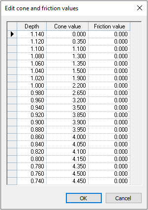
The cone tip resistance and/or the local sleeve friction can also be entered manually by means of a table:
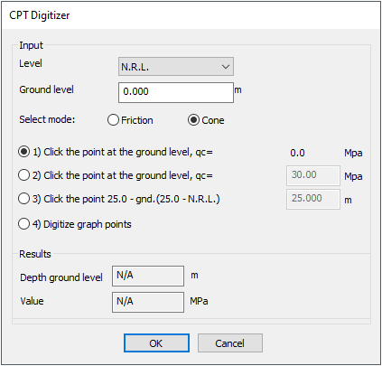
or digitizing diagram magnitudes taken from the pictures (*.jpg; *.jpeg; *.bmp; *.tif; *.gif; *.png), could be opened using standard Open dialog.
Digitizing the cone tip resistance and/or the local sleeve friction diagrams from the pictures, the resistance and/or friction values required of the initial CPT digitizer values can be defined as:
Determining a soil segment arrangement based on cone tip resistances and/or the local sleeve friction values allows several interpretations as:
- Generation of the soil materials based on the friction values;
- Generation of the soil materials based on the cone tip resistance range [qc;inf – qc;sup] analysis;
- Generation of the soil materials based on the cone tip resistance [qc] values.
Basic information concerning the soil properties is by default represented in the NEN-EN 1997-1 table 2b. Using the soil Geotechnics Settings, user defined soil material table(s) could be created and used for the soil segment arrangement generation.
Generation of the soil material segment arrangement performed using the friction values [wc;inf – wc;sup] or cone tip resistance range [qc;inf – qc;sup] analysis is based on the best fit with the average value within the boundaries. In case value persist for the soil recognition is defined outside the range(s), recognition analysis is interrupted or could be continued using the cone tip resistance [qc] or the average friction values. The soil material segment arrangement, performed using the cone tip resistance [qc] values, is based on the looking of the nearest magnitude defined in the Soil materials table.
Using the soil material table(s), the geotechnical designer should have sufficient knowledge of the structure of the soil composition and if required he should make the necessary inquiries for example by using soil drilling or by consulting geological maps.