The purpose of the Column for Isolated Frame project is to perform buckling calculations of a concrete column as part of an isolated frame.
One of the factors which have influence on the buckling behavior of a column is the shape of the acting moments diagram. According to NEN-EN 1992-1-1 #5.8.8.2 the design moment value can be taken as sum of 1st and 2nd order moments. The original EN1992-1-1 formula is extended with the additional rule:
MEd=M0Ed+M2=Max(M0e+M2; M2; M01+0.5M2)
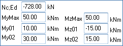
In the user interface for internal forces definition input fields group "Loads" is created. One of these fields is for defining of the axial force value Nc;Ed. The value can be negative (compression) or positive (tension).
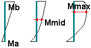
Bending moment values at the ends of a column (M01; M02), at the middle point of a column (Mmid) and the maximum value of the bending moment (MyMax; MzMax) can be provided for both buckling axes Y and Z:
Loads of a column for an isolated frame:
If the value of My(z)Max will be zero, M0e will be calculated according to the equation (5.32) depending on provided My(z)01 and My(z)02 values and for the nominal 2nd order moment calculations will be used factor c = 8.
If the end moments My(z)01 and My(z)02 values will be set to zero, the 1st order moment M0Ed will be equal to the value provided for the maximum bending moment My(z)Max and for the nominal 2nd order moment calculations will be used factor c = 9,6.
For the other cases the 1st order moment M0Ed will be set to a maximum from My(z)02 and My(z)Max and for nominal 2nd order moment calculations will be used factor c = π2.
The nominal second order moment is calculated according to the formula (5.33).