Supports are described on the basis of the degrees of freedom in the X/Y/Z and/or the Xr/Yr/Zr direction. It is indicated per direction whether it is fixed, free or a spring. In this chapter linear spring supports are described. MatrixFrame can also calculate with non-linear spring bearings. These are described in the following chapter.
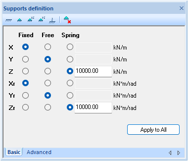
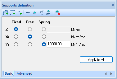
The entry of the degrees of freedom can be done by individually setting fixed, free or spring for the X/Y/Z and/or the Xr/Yr/Zr direction. The screen shot above is for 3D frameworks. The buttons at the top of this dialog are shortcuts. For example, by choosing the leftmost button, the values for X/Y/Z and Xr/Yr/Zr are set to fixed.
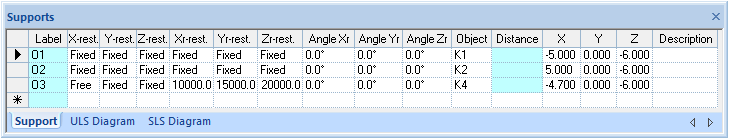
Once the supports have been defined and assigned to the calculation model, they are also visible in the tables. The image above is a screen shot of the supports in the tables for 3D frameworks. The properties of the supports can be adjusted both in the definition screen and in the tables.
Supports at an angle
Input fields for Angle Xr, Angle Yr and Angle Zr are available in the table. In these fields you can enter at which angle (in degrees) a support with respect to the global coordinate system is applied.
Supports under members
In principle, supports are attached to nodes. For project types 1D-Beam and 2D-Grillage, supports can be attached to members with a distance (location) from the support to the start of the member.
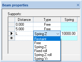
The above dialogue is from 1D beams. During the calculation, these support types are translated into fixed/free/spring support in accordance with the general notation method.
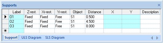
The above dialog is the table representation of the layouts of 2D-Grillage. In this way, supports can be moved freely under the bars, without the schematics of the members and the loads having to be adjusted for this. This property is called 'free support placement' and makes it possible to design optimum positions for foundation piles in a simple manner.
Supports for FEM plates and FEM walls
For FEM plates and FEM walls, not only point-shaped supports are available, but also line and area supports. The above dialogue is from FEM plates. This type of support is further discussed in the chapter FEM plates and FEM walls.
2D-Grillage-specific eccentric placement of the supports
The eccentric shift of the supports is implemented only under the 2D-Grillage package.
The eccentricity of the support refers to a shift in the member axis placement of the support position on the local Y' coordinate of the member. This shift can be defined as either a positive or negative value:
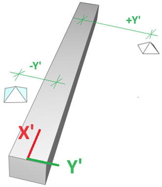
It is important to note that supports located at the beginning and/or end nodes of a member cannot be shifted.
The data input of the eccentric shift is presented in the support definition window and grid table of the advanced properties of the support, such as "Eccentricity: 0.000 m". The default value: 0.000 m is represented by no shifted support position.
The local eccentric shift of the support is represented on the structure drawing, like displacing the support eccentrically to the central axis of the beam/member.
The analysis calculation of the member-located supports is aimed at accounting for the appearance of torsional force because of the eccentrically placed support. With the eccentric supports defined, the advanced analysis option of the reduced torsion is neither meaningful nor encouraged.
Units
The units for supports are:
- Translation springs: kN/m
- Rotation springs: kN·m/rad
Table of degrees of freedom per project type
Project type | Supports degrees of freedom | |||||
X | Y | Z | Xr | Yr | Zr | |
| 1D-Beam | - | - | + | - | + | - |
| 1.5D-Beam | + | + | + | + | + | + |
| 2D-Grillage | - | - | + | + | + | - |
| 2.5D-Grillage | + | + | + | + | + | + |
| 2D-Frame | + | - | + | - | + | - |
| 2D-Truss | + | - | + | - | + | - |
| 2.5D-Frame | + | + | + | + | + | + |
| 3D-Frame | + | + | + | + | + | + |
| 3D-Truss | + | + | + | + | + | + |
| 2D-Plate | - | - | + | + | + | - |
| 2D-Wall | + | + | + | + | + | + |