Rigid links
Rigid links are joints between structural members which does not permit relative motion between them. Rigid links as an axis offset or structural imperfections could be designed and defined as following.
Rigid links can be created in local X', Z'-direction for 2D-Frame, local X', Y'-direction for 2D-Grillage or local X', Y' and Z'-direction for 3D-Frame projects. The length of rigid links must be the local X'-direction (irrespective the beginning or end of the member) to the middle of the member. The length of rigid links in the local Z'-direction or Y'-direction can be both positive and negative depending on the direction of the rigid links.
The distance for the local X'-direction is absolute for Member Begin and Member End and will always result in shortening the elastic part of the member.
The distance in local Z' or Y'-direction is related to the local Z' or Y'-direction of the member.
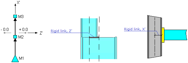
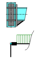
Rigid links position
Rigid links position with respect to release is mentioned in a drawing:
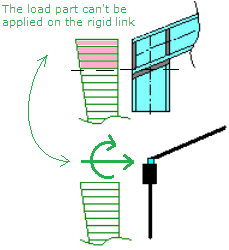
Loading on rigid links
Any kind of external force loading (uniform distributed, distributed, triangular distributed, self-weight, concentrated etc.) and working actions as temperature loading and pre-stressing, could be applied only on flexible (elastic) part of the member. A load applied on the rigid link has to be manually transformed into the nodal load(s).
|
|
| Loading on flexible part of the member | Loading on flexible part of the member and rigid link |
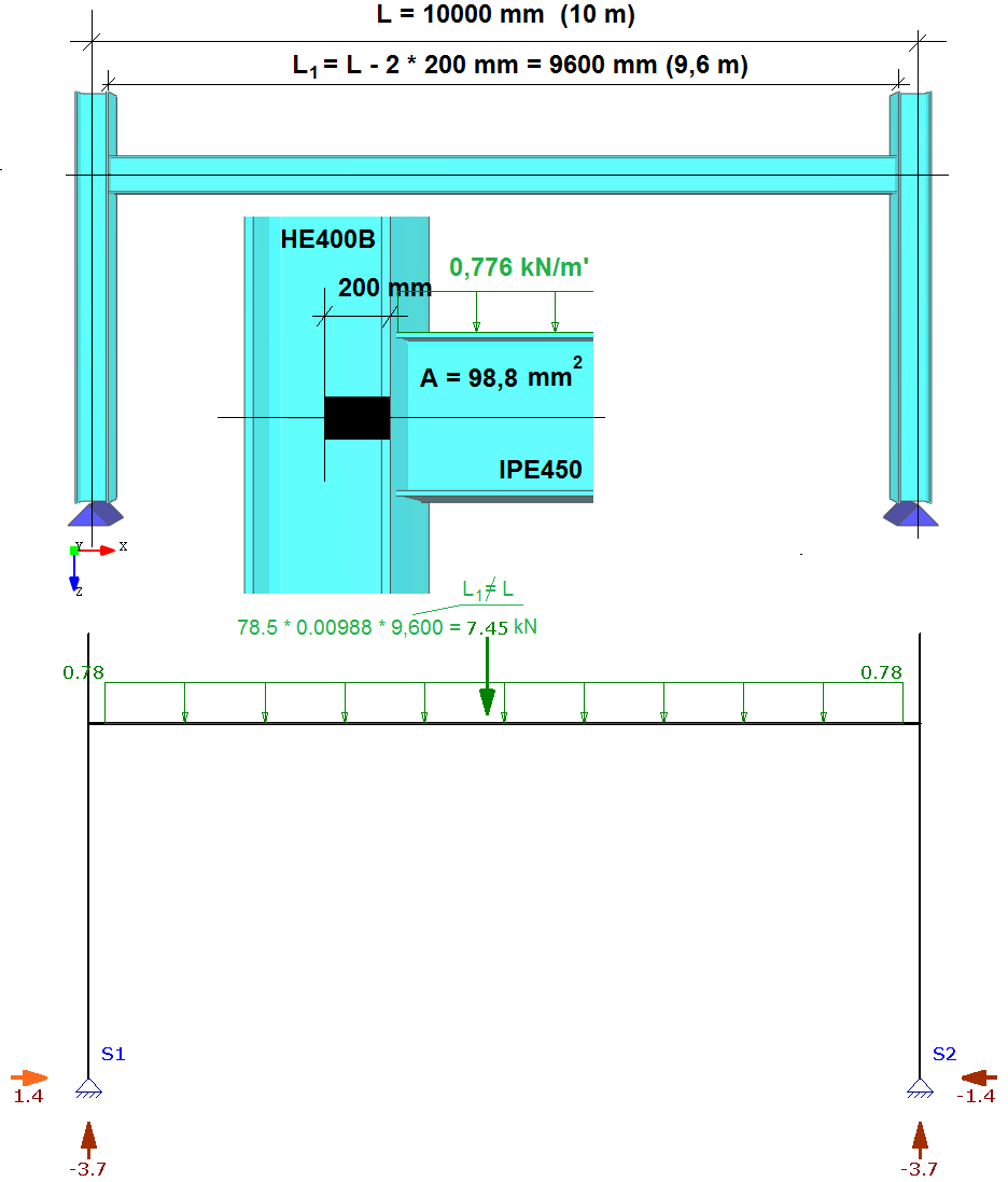
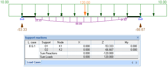
Referencing and interpretation of self-weight load is shown in following example:
By default, the loads are placed on the elastic part of the member within the distance between 0 and L, where L is the length of the elastic part of the member. The distributed loads can be placed on rigid links and/or outside the elastic part of the member using minus (-) notation on the left side of the member and/or distance exceeding the elastic part on the right side of the member:
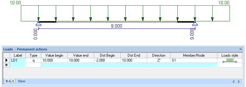
During the calculation, the load part placed on rigid links and/or outside the member is accepted, too:
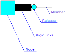
Structural members connection could be represented graphically:
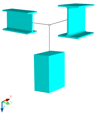
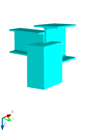
The represented connection constraints is not used during practical design while shifting of structural axis. For correct modeling of connections rigid links should be applied. A rigid link is a rigid bar element that substitutes ideal geometrical interconnection of elements by axis shifting is happening during architectural design.
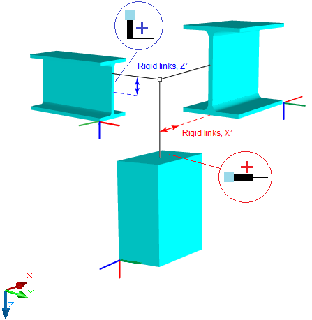
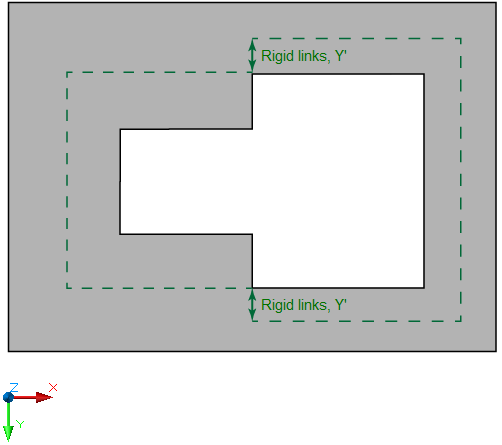
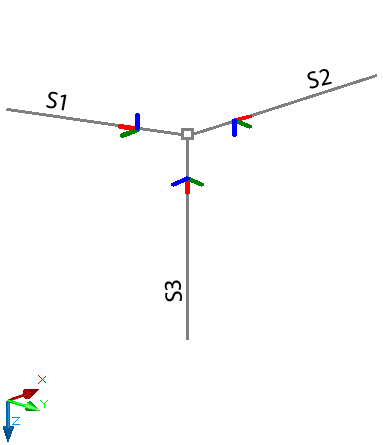
Rigid links in local directions
Rigid links in local directions of the structure in 3D space may look like shown in the pictures below: