The "Buckling length definition" window allows to choose the method:
- Braced
- Sway
- Conservative Braced
- User Defined
for the calculation of buckling length of an element.
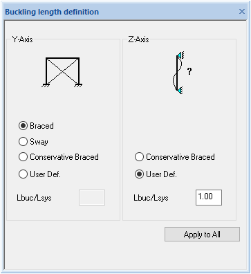
It is possible to choose the method for the calculation of length or to choose the user's method (User Defined) and input the value of the coefficient of length which is to be calculated.
Buckling supports can only be entered for both axes if they have the same values. Otherwise only one axis can have supports.
Support only in Z-axis:
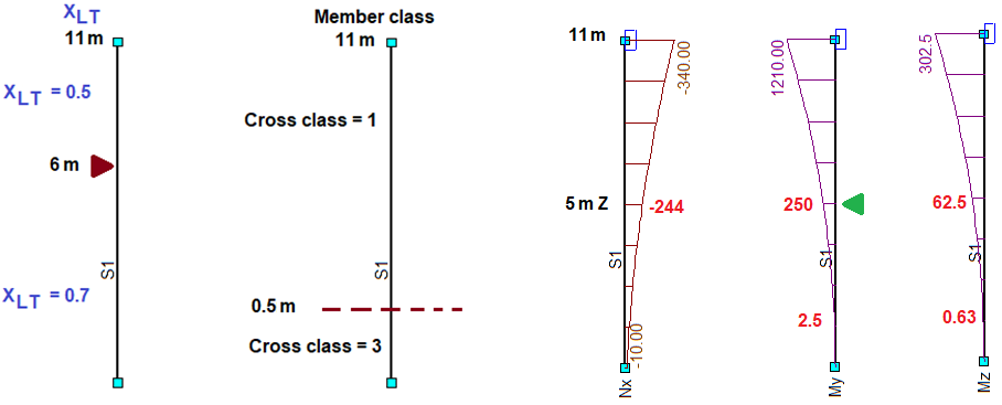
The example is created using a single member 11 m long. On a distance of 6 m the lateral support is placed producing two XLT values. Also, the member contains elastic and plastic ranges. At a point of 5 m the buckling support in Z-axis is placed.
Before starting buckling calculations:
- Cross section classification is performed;
- Lateral buckling check is done to calculate XLT values.
The first step in buckling calculations is to make calculation fields. Initial fields are created using buckling supports. Since single support is defined in Z-axis, two fields are needed. Y-axis doesn’t have supports – the same field is used in both cases.
| Axis | Field 1 | Field 2 | ||
| Begin | End | Begin | End | |
| Y | 0 | 11 | 0 | 11 |
| Z | 0 | 5 | 5 | 11 |
The fields must be split because the member has plastic and elastic classes. If a field is split by classes, these new sub-fields are only used for resistance calculations and maximum bending forces. Buckling forces, buckling length, and Cm factors are calculated from original (“buckling” fields).
| Axis | Field 1.1 | Field 1.2 | Field 2.1 | Field 2.2 | ||||||||||||
| Buckling | Bending | Buckling | Bending | Buckling | Bending | Buckling | Bending | |||||||||
| Begin | End | Begin | End | Begin | End | Begin | End | Begin | End | Begin | End | Begin | End | Begin | End | |
| Y | 0 | 11 | 0 | 0.5 | 0 | 11 | 0.5 | 11 | 0 | 11 | 0 | 0.5 | 0 | 11 | 0.5 | 11 |
| Z | 0 | 5 | 0 | 0.5 | 0 | 5 | 0.5 | 5 | 5 | 11 | 0 | 0.5 | 5 | 11 | 5 | 11 |
The Field 2.1 is invalid because bending field is outside of buckling field in Z-axis. And the range [0; 0.5] is checked by the Field 1.1 so this field is deleted. After removing the Field 2.1 three fields are left for checking. Additional values are needed to perform a check:
- XLT is taken as minimum from Z buckling field;
- Class is taken as maximum from Y- or Z-axis bending field;
- Moments for factors Cm are taken from the buckling field of the opposite axis.
When all values are filled in, we get table below:
| Step | Axis | Buckling field | Bending field | XLT | Class | Forces (6.61 & 6.62) | Moments for factor Cm | ||||||||||
| Begin | End | Buckling length | Begin | End | NEd | My | Mz | My | Mz | ||||||||
| Begin | Middle | Begin | Middle | Begin | Middle | ||||||||||||
| 1 | Y | 0 | 11 | 11 | 0 | 0.5 | 0.7 | 3 | -340 | 2.5 | 0.63 | 0 | 50 | 250 | 0 | 70 | 302.5 |
| Z | 0 | 5 | 5 | 0 | 0.5 | -244 | |||||||||||
| 2 | Y | 0 | 11 | 11 | 0.5 | 11 | 0.7 | 1 | -340 | 250 | 302.5 | 0 | 50 | 250 | 0 | 70 | 302.5 |
| Z | 0 | 5 | 5 | 0.5 | 5 | -244 | |||||||||||
| 3 | Y | 0 | 11 | 11 | 0.5 | 11 | 0.5 | 1 | -340 | 1210 | 302.5 | 250 | 600 | 1210 | 0 | 70 | 302.5 |
| Z | 5 | 11 | 6 | 5 | 11 | -340 | |||||||||||