Structural behavior i.r.t. stability
The structural behavior i.r.t. stability of mono-symmetric channel sections is different from double-symmetric cross sections, such as I-shaped. This difference appears because center of gravity of section and shear center do not coincide.
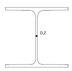
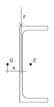
Standard Eurocode 3 requirements for lateral torsional buckling can be used only if load axis is acting in shear center plane. In practice, as well according to the definition in MatrixFrame®, channel sections are loaded in plane of web (eccentrically). No specific design rules are provided in Eurocode 3.
According to the article "Bouwen Met Staal" 202 "Nieuwe toetsingsregel voor de kipstabiliteit van U-profielen" (M.C.M.Bakker at.all) for mono-symmetric sections can be applied the same calculation method like for double-symmetric sections with modified relative slenderness:
This modified relative slenderness consists from ordinary relative slenderness ![]() (like for double-symmetric sections) and from relative slenderness
(like for double-symmetric sections) and from relative slenderness ![]() , which is responsible for torsion influence.
, which is responsible for torsion influence.
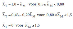
Torsion part of slenderness can be calculated according such formulas:
Buckling factor for lateral torsional buckling:
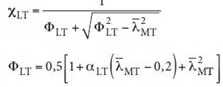
And lateral torsional capacity can be verified:
Equivalent section definition
For other types of sections shapes in the interface of MatrixFrame®, it is possible to choose an equivalent section which corresponds in best way to the behavior of the original section. If the section shape doesn't fit the requirements of the code for stability check, it is possible to choose an equivalent section in tab General in the Steel code check grid. Properties of this equivalent section will be used in stability check calculations:
Default equivalent section
1. Tapered or assembled sections: the shape and dimensions from the cross section at the end of the beam is taken in case of a cantilever, in other cases the middle of the span is taken.
2. IFB-sections:
- Hody and THQ as parametric Square tube with the same dimensions ht, Bb, tf, tw;
- ASB, IFB-A, IFB-B, SFB as a parametric I-shape with the same dimensions hB, Bb, tf, tw.
3. In case of not double symmetric sections a parametric U-shape is used, with equal section dimensions summarized: for example, L-shape the Height, tw and tf could be used 1-to-1, but Width should be divided by 2, as L-shape has only 1 flange and U-shape 2.
4. Equivalent section properties are used only for calculations of lateral buckling parameters. For cross section resistance (Eurocode chapter 6.2) and for uniform members in compression buckling check (Eurocode chapter 6.3.2) will be used original properties (not equivalent) of cross section.
For more information about cross section definition see Parametric cross sections and Database cross sections articles.