The Tube connection – a vertical tube welded to a horizontal tube.
Tube joint connection types:
- X joint
- T Y joint
- KN joint
- KT joint
It is necessary to select one of the variants for the joint connection creation. The setting of parameters for each of the two structural elements (beam1, beam2, ...) of the created connection:
|
Parameter |
Unit |
Description |
|
Angle |
° |
The Angle takes the value in the interval [0°; 180°]. This allows to change the value of the angle so that it does not exceed the lower and upper bounds of the interval. An inclination of the angle for the connected member is limited on [0°; 180°] for a design reason also for a proper design of a haunch. If the angle entered is a decimal fraction, the value will be rounded to the nearest tenth, i.e. to one number after the comma. The Angle is calculated from the left side and is shown in the following figure: 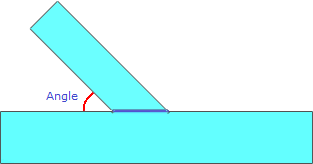 |
|
Section
|
- |
List of available sections is dependent on technical modules. Could be extended on request, or by updating a product table. It allows to select the shape and dimensions of the joint connection structure sections. The restrictions and the rules for the different sections are used for design reason |
|
Material |
- |
Steel material name is using for code check calculation and supported by EN 1993-1-1#Table 3.1 and related national annexes such as NEN-EN 1993-1-1#3.1. Items listed in a Material drop down list depend on chosen code or/and national annex |
|
Eccentricity |
mm |
The distance designed in the following figure: 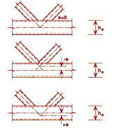 |
|
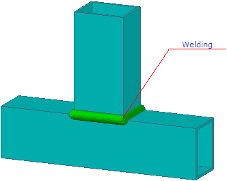
Welding |
mm |
The throat thickness of the horizontal weld at the intersection of two connected members:
|
Weld steel material name is used for code check calculation and supported by EN 1993-1-1#Table 3.1 and related national annexes such as NEN-EN 1993-1-1#3.1. Weld steel list depend on chosen code or/and national annex.