The Bolted-Splice joint connection – two end plates connected together by bolts and each of them welded to the end of its own beam section. Each bolt-row consists of two bolts.
Bolted-Splice joint connection types:
- Symmetric beam
- Asymmetric beam
- Symmetric column
- Asymmetric column
The symmetric joint connection model as the symmetric geometry means an identical angle of the connected members, length etc. as well as different loads left/right. The asymmetric joint connection model means not only different angle of the connected members, length etc., but also different geometrical parameters for each structural member and different loads.
It is necessary to select one of eight variants for the joint connection creation. The setting of parameters for each of the two structural elements (column, beam) of the created connection:
|
Parameter |
Unit |
Description |
|
Angle |
° |
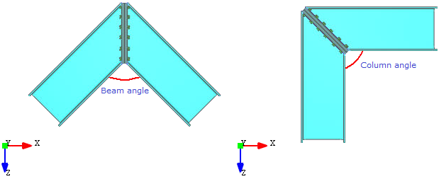
The Angle takes the value in the interval [45°; 180°]. This allows to change the value of the angle so that it does not exceed the lower and upper bounds of the interval. An inclination of the angle for the connected member is limited on [45°; 180°] for a design reason also for a proper design of a haunch. If the angle entered is a decimal fraction, the value will be rounded to the nearest tenth, i.e. to one number after the comma. The angle is shown in the following figure:
|
|
Section
|
- |
Only I-shapes. List of available sections is dependent on technical modules. Could be extended on request, or by updating a product table. It allows to select the shape and dimensions of the joint connection structure sections. The restrictions and the rules for the different sections are used for design reason |
|
Material |
- |
Steel material name is using for code check calculation and supported by EN 1993-1-1#Table 3.1 and related national annexes such as NEN-EN 1993-1-1#3.1. Items listed in a Material drop down list depend on chosen code or/and national annex |
|
Length |
mm |
The length of the joint connection structure is doing influence into the calculation of rotation angle (Phi) of M-Phi diagram. Default value of the length (L=1000) is coming from MatrixFrame® in case of integrated calculation and take as length of connected member: 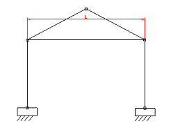 |