If "Loads" main branch in the "Plate" tree is marked, the table of loading properties is displayed on the right side of the window:
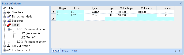
- Region – refers to the designed region of the plate containing a unique boundary condition set. The region itself is described in the lower branch(es) of the "Loads" tree ;
- Label – refers to the unique boundary conditions set of a loading;
- Type – refers to plate geometry design object type (region, polyline or point) on what boundary condition is applied;
- Type – refers to the loading type;
- Value Begin – magnitude of a load vector on the begin point of a polyline. In case region or point loading is defined only Value Begin should be defined;
- Value End – magnitude of a load vector on the end point of a polyline. In case region or point loading is defined only Value Begin should be defined;
- Direction – refers to a load direction vector.
All the defined loads are related to the load cases located on the tabs in the bottom part of the table.
Right mouse click on selected "Loads" tree branch header allows to insert new loading region. The objects of polylines and points are described as subset of a region.
Lower level of main "Lioads" tree branch is used to estimate/change coordinates for every vertex of a loading region, polyline or point. Vertexes are sequentially listed it the table to define regions, polylines or points to which the loads are assigned.
The selected loading reference label in the "Loads" tree allows to remove load objects with their boundary conditions through the context menu (right mouse click). The selected vertex(es) in the table allows to delete or insert new vertexes through the context menu (right mouse click).
Coordinates of vertex(es) are defined in the global coordinate system referenced to X=0 and Y=0 point.
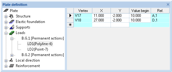
Table of coordinates is supporting clipboard copy/paste functionality.