Design of the plate is based on physical sense of the plate without explicit knowledge about usage of Finite Element Method.
During design process designer is working only with plate geometry design objects on which different physical objects like plate cross section, boundary condition, loading etc. could be applied. Plate geometry design objects are describing placement of physical objects. Plate geometry objects could be used as follow:
- Region, as domain object of the plate plane
- Polyline, as continuous set of straight line objects
- Point, as point object. Point object is describing standalone object so far vertex(es) of polyline
Design workflow
By assigning physical properties like section properties, boundary conditions etc. on single plate geometry design object smart selection of object is working. Smart selection is indicated by changing of object color in the neighborhood of mouse cursor position.
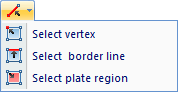
Assignment of properties on multiple objects is possible after pre-selecting plate geometry design objects: plate region, border line or vertex from "Select" list: