Formslab: top reinforcement:
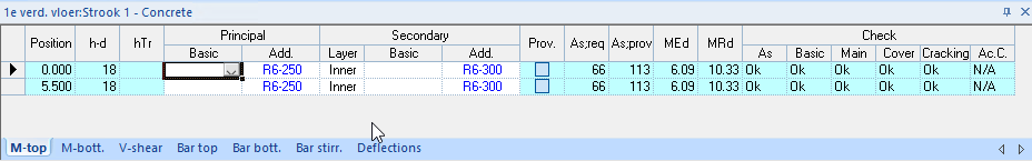
- Position: normative cut for which the reinforcement is calculated.
- h-d (mm): calculated distance from the top of the concrete to the center of the reinforcement. Calculates the internal lever arm.
- hTr (mm): height of the lattice girder. This only applies to the lower reinforcement.
- Principal: Principal reinforcement
- Basic: basic reinforcement, which runs the full length of the beam.
- Add.: additional reinforcement, which runs over a part of the beam and can be reduced based on the moments coverage line.
- Secondary: secondary reinforcement
- Layer: the location of the secondary reinforcement: in the 1st layer (outer) or the 2nd layer (inner).
- Basic: secondary reinforcement which runs over the full width of the beam.
- Add.: additional secondary reinforcement which runs over the full width of the beam.
- Prov.: if available, this can be used to define the reinforcement as already present, after which the required reinforcement is calculated.
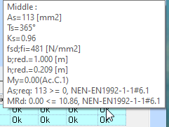
- As;req: the required reinforcement in mm2.
- As;prov: the applied reinforcement in mm2.
- MEd: moment in the cut in kNm.
- MRd: moment resistance with the applied reinforcement in kNm.
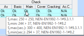
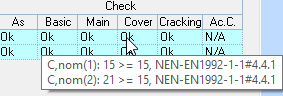
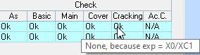
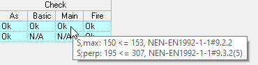
- Check: the result of the norm-related checks is shown here. The checks are visible in the tooltip.
- As: check of required and provided reinforcement.
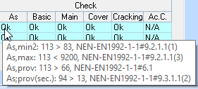
- Basic: check of basic reinforcement.
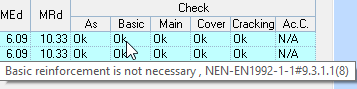
- Main: check of the main reinforcement.
- Cover: checking the applied cover against the required nominal cover.
- Cracking: check of the crack width based on the setting under concrete options.
- Fire: checking the required fire resistance with reduced cross section and steel stress.
- As: check of required and provided reinforcement.
Formslab: bottom reinforcement:
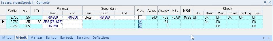
- Position: normative cut for which the reinforcement is calculated.
- h-d (mm): calculated distance from the bottom of the concrete to the center of the reinforcement. Calculates the internal lever arm.
- hTr (mm): height of the lattice girder. This only applies to the lower reinforcement.
- Principal: principalreinforcement
- Basic: basic reinforcement, which runs the full length of the beam.
In this example:
The 2R8-(75+675) are the lower bars of the lattice girder
And the R6-750 is the top bar of the lattice girder. - Add.: additional reinforcement, which runs over part of the beam and can be reduced based on the moments cover line.
- Basic: basic reinforcement, which runs the full length of the beam.
- Secondary : secondary reinforcement
- Layer: the location of the secondary reinforcement: in the 1st layer (outer) or the 2nd layer (inner).
- Basic: secondary reinforcement which runs over the full width of the beam.
- Add.: secondary reinforcement which runs over the full width of the beam.
- Prov: if available, this can be used to define the reinforcement as already present, after which the required reinforcement is calculated. A lattice girder is fixed by default.
Formslab: V-shear:
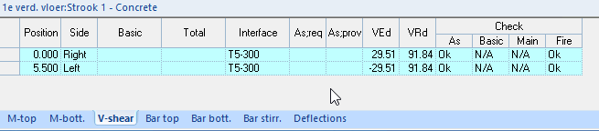
With the strip type "Slab" no stirrups are calculated, but a check is made on the shear force.
- Position: decisive cut where the shear force is checked.
- Side: right or left of the cut.
- Basic: the basic stirrup is shown here for reinforcement type "Strip" or "Beam". (e.g. R8-300).
- Total: the total stirrup is shown here for reinforcement type "Strip" or "Beam". (e.g. R8-150).
- Interface: here the reinforcement of the lattice girder is shown which is processed in the control of the shear between the precast concrete and poured concrete.
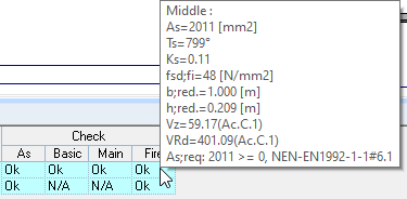
- As;req: the required shear reinforcement is shown here, if applicable.
- As;prov: the applied shear reinforcement is shown here, if applicable.
- VEd: acting shear force in the cut in kN.
- VRd: shear resistance based on the applied reinforcement in kN.
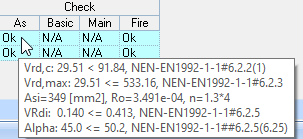
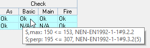
- Check: the result of the norm-related checks are shown here. The checks are visible in the tooltip.
- As: check of required and applied reinforcement.
- Basic: check of basic reinforcement.
- Main: check of the main reinforcement.
- Fire: checking the required fire resistance with reduced cross section and steel stress.
- As: check of required and applied reinforcement.
Formslab: Position of the reinforcement:
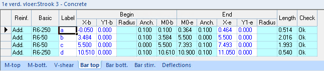
Reinf.: indication of whether it concerns basic or additional reinforcement.
- Basic: the applied reinforcement is shown.
- Label: the label associated with the reinforcement shown in the image.
- Begin: position where the reinforcement begins.
- X-b: position in the "X" direction.
- Y-b: length of the deflection.
- Radius: radius of the deflection.
- Anch.: calculated anchorage length.
- M0-b: moments zero point start:
- End: position where the reinforcement ends.
- M0-b: moments zero point end:
- Anch.: calculated anchorage length.
- X-e: position in the "X" direction.
- Y-e: length of the deflection.
- Radius: radius of the deflection.
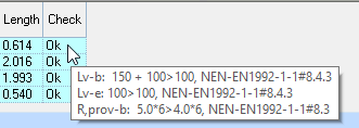
- Length: total bar length.
- Check: The tooltip shows the checks for "OK" and "Error".
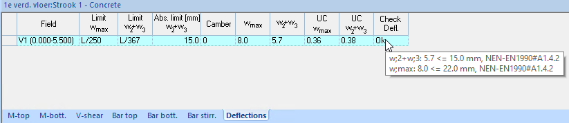
Formslab: deflections:
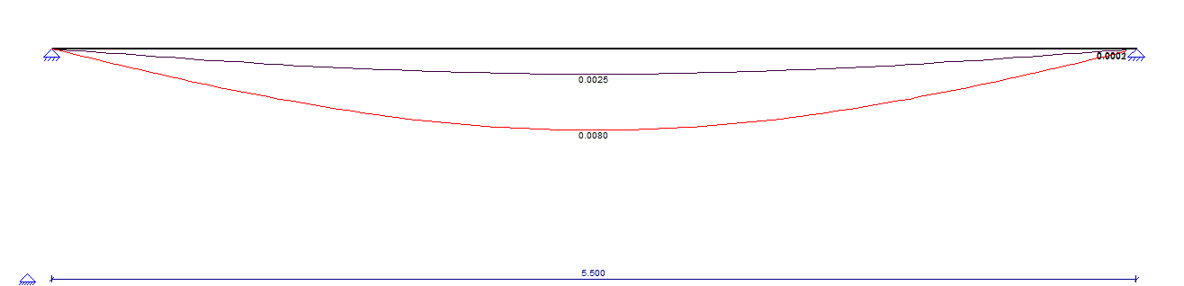
- Tab deflections:

- Field: here is the field with the start and end position where the deflection was tested.
- Limit wmax: the normative test value for wmax.
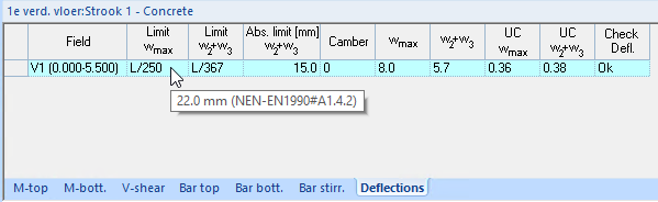
- Limit w2+w3: the normative test value for w2+w3 or absolute limit.
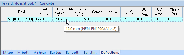
- abs. limit [mm] w2+w3: user-specified value that overrides the normative test value.
- Camber: User-specified camber value in mm.
- Wmax: calculated value with in the tooltip the explanation from which load combination the different values have been determined.
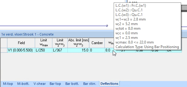
- W2+w3: calculated value with in the tooltip the explanation from which load combination the different values have been determined.
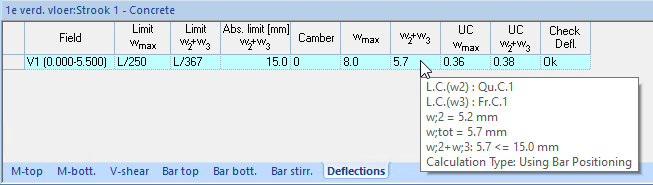
- Wmax: uniticheck wmax.
- W2+w3: unitycheck w2+w3.
- Check Defl.: The tooltip shows the checks for "OK" and "Error".